
Page 61 - Modular design for machine tools
P. 61
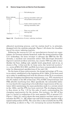
32   Modular Design Guide and Machine Tools Description

                                    Dial indexing type


               Rotary indexing      Indexing (monolithic) table type
               machines
                                    with peripheral allocated units

                                    Center-column machine with
                                    indexing (monolithic) table


                                    Three-way machine with
                                    indexing table
                (Variants)
                                    Trunnion type
               Figure 1-20 Classification of rotary indexing machines.


               allocated machining process, and the station itself is, in principle,
               designed with the modular principle. Figure 1-20 shows the classifica-
               tion of the rotary indexing machine.
                 Following the success in U.S. car manufacturers beyond our expec-
               tations, the German industry launched, under the strong stimulus of the
               U.S. technology, the keen attempt to advance the BBS for the TL.
               Actually, a machine tool committee within VDI (Vereinigte Deutscher
               Ingenier) carried out these activities. As a result, VDI was able to stan-
               dardize the base, sliding unit, spindle head, gang head, and so on, as
               shown in Fig. 1-21(a) and (b). In these units, the “preferred numbers,”
               i.e., series of R05, R10, R20, and R40, have been recommended to deter-
               mine the dimensional specifications of the unit [16].
                 On the basis of these achievements, the design technology of TL was,
               to an extent, established in the beginning of the 1960s. It has been used
               up to today by modifying itself with the advance of the TL in accordance
               with the changing manufacturing requirements, e.g., FTL consisting of
               the NC station or the MC of line type, FTL of FMC-integrated type and
               FML (flexible machining line). More specifically, the automobile indus-
               try was faced with responding to the individual requirements of the cus-
               tomer while maintaining the mass production mode to a certain extent
               in the 1980s, and the FTL has been contrived. The developing history
               is thus shown in Fig. 1-22 for the sake of easily understanding the
               changing requirements for the station. For instance, the MC of line
               type is a kernel in realization of the most popular FTL at present [17].
               Figure 1-23(a), (b), and (c) shows the most popular machine tools to sys-
               tematize the FTL, i.e., MC of line type and head changer, together with a
               typical configuration of FTL. The same idea is also available for the FTL
               for grinding, as shown in Fig. 1-24, increasing the system flexibility by