
Page 133 - Multidimensional Chromatography
P. 133
Coupled-Column Liquid Chromatography 125
(Step 2) Introduce heart-cut to the analytical column and detector. At the prede-
termined time interval, which was previously calculated by eluting analyte standards
without the analytical column, i.e. the onset of the heart-cut, valve B is closed to
divert the precolumn effluent to the analytical column.
(Step 3) Bypass the precolumn and detection of the analyte of interest. When all
of the analytes of interest have been eluted from the precolumn, valve A is opened so
that the eluent stream is diverted to valve B, which is immediately opened to allow
eluent from valve A to flow into the analytical column, thus bypassing the precol-
umn.
(Step 4) Precolumn clean-up not shown in Figure 5.4. After the heart-cut analytes
have been transferred to the analytical column, a step-gradient programme is used to
flush the precolumn of the more strongly retained compounds. An additional pump
configuration makes precolumn clean-up possible while the analysis is running.
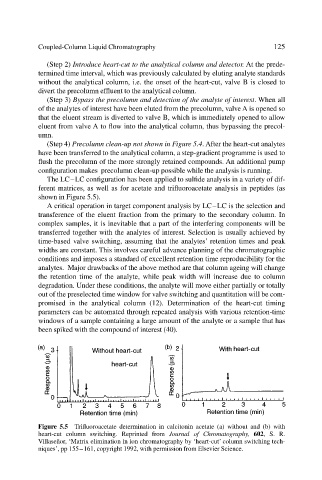
The LC–LC configuration has been applied to sulfide analysis in a variety of dif-
ferent matrices, as well as for acetate and trifluoroacetate analysis in peptides (as
shown in Figure 5.5).
A critical operation in target component analysis by LC–LC is the selection and
transference of the eluent fraction from the primary to the secondary column. In
complex samples, it is inevitable that a part of the interfering components will be
transferred together with the analytes of interest. Selection is usually achieved by
time-based valve switching, assuming that the analytes’ retention times and peak
widths are constant. This involves careful advance planning of the chromatographic
conditions and imposes a standard of excellent retention time reproducibility for the
analytes. Major drawbacks of the above method are that column ageing will change
the retention time of the analyte, while peak width will increase due to column
degradation. Under these conditions, the analyte will move either partially or totally
out of the preselected time window for valve switching and quantitation will be com-
promised in the analytical column (12). Determination of the heart-cut timing
parameters can be automated through repeated analysis with various retention-time
windows of a sample containing a large amount of the analyte or a sample that has
been spiked with the compound of interest (40).
Figure 5.5 Trifluoroacetate determination in calcitonin acetate (a) without and (b) with
heart-cut column switching. Reprinted from Journal of Chromatography, 602, S. R.
Villaseñor, ‘Matrix elimination in ion chromatography by ‘heart-cut’ column switching tech-
niques’, pp 155–161, copyright 1992, with permission from Elsevier Science.