
Page 338 - Multidimensional Chromatography
P. 338
328 Multidimensional Chromatography
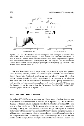
Figure 12.21 SFC–GC heart-cut analysis of chrysene from a complex hydrocarbon mix-
ture: (a) SFC trace (UV detection); (b) GC trace without heart-cut (100% transfer); (c) GC
trace of heart-cut fraction (flame-ionization detection used for GC experiments). Reprinted
from Journal of High Resolution Chromatography, 10, J. M. Levy et al., ‘On-line multidimen-
sional supercritical fluid chromatography capillary gas chromatography’, pp. 337–341, 1987,
with permission from Wiley-VCH.
SFC–GC has also been used for group-type separations of high-olefin gasoline
fuels, including saturates, olefins, and aromatics (25). The SFC–GC characteriza-
tion of the aromatic fraction of gasoline fuel was carried out by using CO 2 on four
packed columns in series, i.e. silica, Ag -loaded silica, cation-exchange silica and
NH 2 silica. The heart-cut fractions were transferred into a capillary column coated
with a methyl polysiloxane stationary phase, with cryofocusing at 50 °C being used
for focusing during the transfer into the GC system. The SFC–FID and GC–FID
chromatographs are shown in Figure 12.22.
12.11 SFC–SFC APPLICATIONS
An on-line SFC–SFC coupled technique involving a rotary valve interface was used
to provide an efficient separation of coal tar (see in Figure 12.23) (26). A schematic
diagram of the multidimensional packed capillary to open tubular column SFC–SFC
system is shown in Figure 12.24. The rotary valve interface was used to provide the
flexibility of using two independently controlled pumps, which gave an increased
performance of the system when compared to the traditional one-pump system. In
addition, an on-column cryogenic trap was used to suppress efficiency losses due to
the first packed column. This cryogenic unit efficiently traps the selected fractions
and focuses the sample, then allowing the transfer of the fractions into a narrow band