
Page 138 - Offshore Electrical Engineering Manual
P. 138
Reciprocating Pumps and Compressors 125
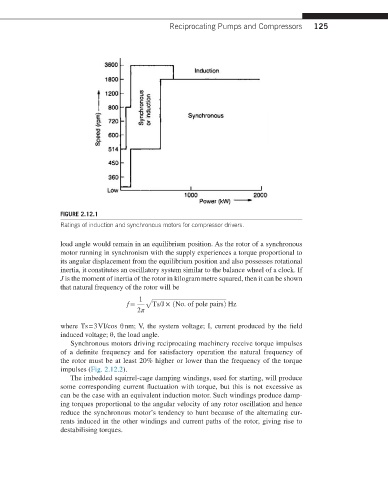
FIGURE 2.12.1
Ratings of induction and synchronous motors for compressor drivers.
load angle would remain in an equilibrium position. As the rotor of a synchronous
motor running in synchronism with the supply experiences a torque proportional to
its angular displacement from the equilibrium position and also possesses rotational
inertia, it constitutes an oscillatory system similar to the balance wheel of a clock. If
J is the moment of inertia of the rotor in kilogram metre squared, then it can be shown
that natural frequency of the rotor will be
1 √
f = Ts/J × (No. of pole pairs) Hz
2π
where Ts = 3 VI/cos θ nm; V, the system voltage; I, current produced by the field
induced voltage; θ, the load angle.
Synchronous motors driving reciprocating machinery receive torque impulses
of a definite frequency and for satisfactory operation the natural frequency of
the rotor must be at least 20% higher or lower than the frequency of the torque
impulses (Fig. 2.12.2).
The imbedded squirrel-cage damping windings, used for starting, will produce
some corresponding current fluctuation with torque, but this is not excessive as
can be the case with an equivalent induction motor. Such windings produce damp-
ing torques proportional to the angular velocity of any rotor oscillation and hence
reduce the synchronous motor’s tendency to hunt because of the alternating cur-
rents induced in the other windings and current paths of the rotor, giving rise to
destabilising torques.