
Page 45 - Op Amps Design, Applications, and Troubleshooting
P. 45
28 BASIC CONCEPTS OF THE INTEGRATED OPERATIONAL AMPLIFIER
cause voltage drops across the distributed inductance in the power and ground
lines. Since the frequencies are generally in the megahertz range, substantial
inductive reactance and therefore voltage drop may result.
The high-frequency voltage drops just described cause several problems includ-
ing the following:
1. The noise and/or high-frequency signal from one circuit affects the supply
voltage for another circuit. The circuits are now coupled rather than being
independent as theory would suggest.
2. The output of a circuit can be shifted in phase and coupled back to its input.
If the circuit has sufficient gain, then we will have all the conditions
necessary for sustained oscillation.
3. The overall power distribution circuit tends to behave like a loop antenna
and radiates the high-frequency signals into adjacent circuits or systems.
Section 1.5.4 specifies the use of an adequate wire size. This primarily affects
the DC resistance of the wire. By running the V cc line and the ground return phys-
ically close together as suggested in Section 1.5.4, however, you can reduce the
actual inductance of the supply lines and thus improve the high-frequency perfor-
mance. Additionally, by keeping the supply lines close together, you reduce the
loop area of an effective loop antenna and dramatically reduce radiations from the
power supply loop.
Sections 1.5.2,1.5.3, and 1.5.4 all recommend the use of short lead lengths.
Shorter lead length directly reduces the value of distributed inductance and so
reduces the magnitude of the high-frequency voltage drop problem.
You are now in a position to appreciate the value of decoupling components.
The intent of decoupling is to further isolate one circuit from another with refer-
ence to the DC power distribution lines. We will examine decoupling at two
important points in the system:
1. Circuit decoupling
2, Power-entry decoupling
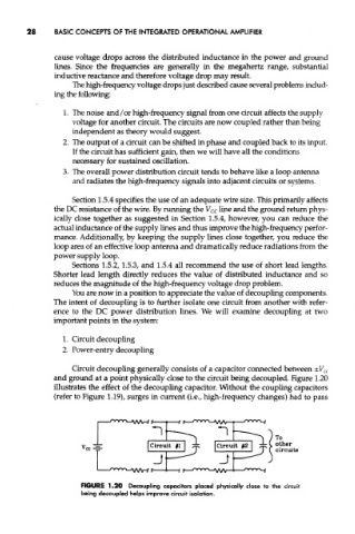
Circuit decoupling generally consists of a capacitor connected between ±V CC
and ground at a point physically close to the circuit being decoupled. Figure 1.20
illustrates the effect of the decoupling capacitor. Without the coupling capacitors
(refer to Figure 1.19), surges in current (i.e., high-frequency changes) had to pass
FIGURE 1.20 Decoupling capacitors placed physically close to the circuit
being decoupled helps improve circuit isolation.