
Page 72 - Optical Communications Essentials
P. 72
Optical Fibers
62 Chapter Four
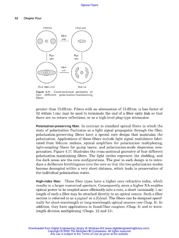
Figure 4.11. Cross-sectional geometry of
four different polarization-maintaining
fibers.
greater than 15dB/cm. Fibers with an attenuation of 15dB/cm (a loss factor of
32 within 1cm) may be used to terminate the end of a fiber optic link so that
there are no return reflections, or as a high-level plug-type attenuator.
Polarization-preserving fiber. In contrast to standard optical fibers in which the
state of polarization fluctuates as a light signal propagates through the fiber,
polarization-preserving fibers have a special core design that maintains the
polarization. Applications of these fibers include light signal modulators fabri-
cated from lithium niobate, optical amplifiers for polarization multiplexing,
light-coupling fibers for pump lasers, and polarization-mode dispersion com-
pensators. Figure 4.11 illustrates the cross-sectional geometry of four different
polarization-maintaining fibers. The light circles represent the cladding, and
the dark areas are the core configurations. The goal in each design is to intro-
duce a deliberate birefringence into the core so that the two polarization modes
become decoupled within a very short distance, which leads to preservation of
the individual polarization states.
High-index fiber. These fiber types have a higher core refractive index, which
results in a larger numerical aperture. Consequently, since a higher NA enables
optical power to be coupled more efficiently into a core, a short (nominally 1-m)
length of such a fiber may be attached directly to an optical source. Such a fiber
section is referred to as a pigtail or a flylead. The fibers can be designed specif-
ically for short-wavelength or long-wavelength optical sources (see Chap. 6). In
addition, they have applications in fused-fiber couplers (Chap. 8) and in wave-
length division multiplexing (Chaps. 12 and 13).
Downloaded from Digital Engineering Library @ McGraw-Hill (www.digitalengineeringlibrary.com)
Copyright © 2004 The McGraw-Hill Companies. All rights reserved.
Any use is subject to the Terms of Use as given at the website.