
Page 188 -
P. 188
Speech Recognition 175
Vcc
R4
5.6KΩ
3
5 12
+
U3 2 U7d
4 LM339 9 10
– R3 10
R5 10KΩ 4049
15KΩ
U7c
7 6
9
4049
U7b
LED Input 5 4
8
4049
Vcc
1 14 U7a
U4a 3 3 2
A 2 4011 8 4049 7
U4c 10
9 4011
B 6
U4b 4 14 U6f 15
5 4011 6
C 4049
D Output
U6e
13 11 12 5
U4d 11
12 4011 Vcc 4049
U6d
R11 9 10
14 4
10 VDD U5 4.7KΩ Vcc 4049
3 RB4 4 24
11 RA4 MCLR' X1
D RB5 OSC1 16 7 U6c 6
15 4049 3
C OSC2 4MHz Q10 11
Q9 10
9
B Q8 8 U6b
2 RA3 RB3 9 20 Q7 7 5 4 2
1 8 21 D Q6 6 4049
A 18 RA2 RB2 7 22 C Q5 5
17 RA1 RB1 6 23 B Q4 4
RA0 RB0/INT A Q3 3
VSS 12 Q2 2 3 U6a 2
5 Q1 1
GND PIC16F84 18 19 Q0 1 4049
74154
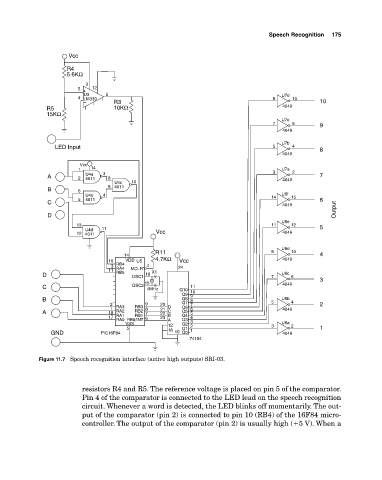
Figure 11.7 Speech recognition interface (active high outputs) SRI03.
resistors R4 and R5. The reference voltage is placed on pin 5 of the comparator.
Pin 4 of the comparator is connected to the LED lead on the speech recognition
circuit. Whenever a word is detected, the LED blinks off momentarily. The out
put of the comparator (pin 2) is connected to pin 10 (RB4) of the 16F84 micro
controller. The output of the comparator (pin 2) is usually high (�5 V). When a