
Page 244 - Automobile Mechanical and Electrical Systems Automotive Technology Vehicle Maintenance and Repair (Vehicle Maintenance Repr Nv2) by Tom Denton
P. 244
2
228 Automobile mechanical and electrical systems
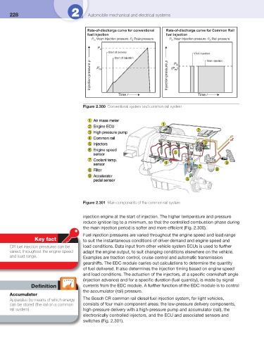
Rate-of-discharge curve for conventional Rate-of-discharge curve for Common Rail
fuel injection fuel injection
P Mean injection pressure. P Peak pressure. P Mean injection pressure. P Rail pressure.
m S m R
P s
Start of delivery
Pilot injection
Start of Injection P R Main injection
Injection pressure p P m Injection pressure p (P )
m
Time r Time r
Figure 2.300 Conventional system and common rail system
Figure 2.301 Main components of the common rail system
injection engine at the start of injection. The higher temperature and pressure
reduce ignition lag to a minimum, so that the controlled combustion phase during
the main injection period is softer and more effi cient ( Fig. 2.300 ).
Fuel injection pressures are varied throughout the engine speed and load range
Key fact to suit the instantaneous conditions of driver demand and engine speed and
CR fuel injection pressures can be load conditions. Data input from other vehicle system ECUs is used to further
varied, throughout the engine speed adapt the engine output, to suit changing conditions elsewhere on the vehicle.
and load range. Examples are traction control, cruise control and automatic transmission
gearshifts. The EDC module carries out calculations to determine the quantity
of fuel delivered. It also determines the injection timing based on engine speed
and load conditions. The actuation of the injectors, at a specifi c crankshaft angle
(injection advance) and for a specifi c duration (fuel quantity), is made by signal
Defi nition currents from the EDC module. A further function of the EDC module is to control
the accumulator (rail) pressure.
Accumulator
Apparatus by means of which energy The Bosch CR common rail diesel fuel injection system, for light vehicles,
can be stored (the rail on a common consists of four main component areas: the low-pressure delivery components,
rail system). high-pressure delivery with a high-pressure pump and accumulator (rail), the
electronically controlled injectors, and the ECU and associated sensors and
switches ( Fig. 2.301 ).