
Page 283 - Automobile Mechanical and Electrical Systems Automotive Technology Vehicle Maintenance and Repair (Vehicle Maintenance Repr Nv2) by Tom Denton
P. 283
3
Electrical systems 267
Figure 3.19 Wiring and connectors on a vehicle
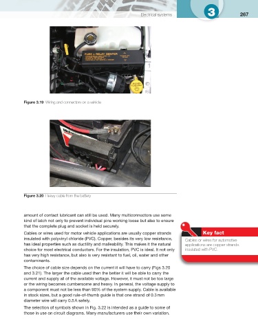
Figure 3.20 Heavy cable from the battery
amount of contact lubricant can still be used. Many multiconnectors use some
kind of latch not only to prevent individual pins working loose but also to ensure
that the complete plug and socket is held securely.
Cables or wires used for motor vehicle applications are usually copper strands Key fact
insulated with polyvinyl chloride (PVC). Copper, besides its very low resistance,
Cables or wires for automotive
has ideal properties such as ductility and malleability. This makes it the natural applications are copper strands
choice for most electrical conductors. For the insulation, PVC is ideal. It not only insulated with PVC.
has very high resistance, but also is very resistant to fuel, oil, water and other
contaminants.
The choice of cable size depends on the current it will have to carry ( Figs 3.20
and 3.21 ). The larger the cable used then the better it will be able to carry the
current and supply all of the available voltage. However, it must not be too large
or the wiring becomes cumbersome and heavy. In general, the voltage supply to
a component must not be less than 90% of the system supply. Cable is available
in stock sizes, but a good rule-of-thumb guide is that one strand of 0.3 mm
diameter wire will carry 0.5 A safely.
The selection of symbols shown in Fig. 3.22 is intended as a guide to some of
those in use on circuit diagrams. Many manufacturers use their own variation.