
Page 396 - Petrophysics 2E
P. 396
364 PETROPHYSICS: RESERVOIR ROCK PROPERTIES
Defining the relative wetting behavior of fluids in a rock is complex
because there are variations of spreading behavior at points, or areas,
within the rock and the measured wettability is an average of the physical
and chemical interactions of the fluids. The relative amounts of rock
surface wet by one fluid or the other define the overall wettability of the
system [14-17, 551.
Assume that a preferentially water-wet rock core is saturated with
20% water and 80% oil. In this case, the adhesion tension is positive
(oso > osw) and the contact angle is less than 90". If this water-wet core
is contacted with water, some oil will be spontaneously expelled from
the core as water is imbibed along the walls and into the smaller pores
until a state of equilibrium is attained between the solid-fluid specific
surface energies (interfacial tensions). The wetting fluid entering the
core will accumulate in the pores that create the greatest fluid-fluid
interfacial curvature consistent with Equation 6.1; thus, the wetting
phase accumulates in the smallest pores.
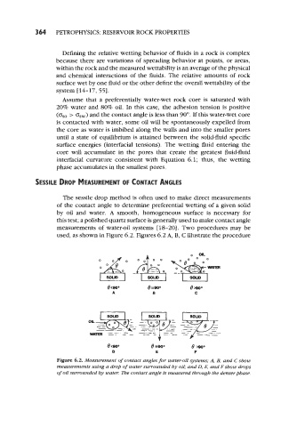
SESSILE DROP MEASUREMENT CONTACT ANGLES
OF
The sessile drop method is often used to make direct measurements
of the contact angle to determine preferential wetting of a given solid
by oil and water. A smooth, homogeneous surface is necessary for
this test; a polished quartz surface is generally used to make contact angle
measurements of water-oil systems [ 18-20]. Two procedures may be
used, as shown in Figure 6.2. Figures 6.2 A, B, C illustrate the procedure
e (900 e -800 8 >800
D E F
Figure 6.2. Measurement of contact angles for water-oil systems; A, B, and C sbow
measurements using a drop of water surrounded by oil; and 0, E, and F sbow drops
of oil surrounded by water. me contact angle is measured through the denserpbase.