
Page 458 - Petrophysics
P. 458
426 PETROPHYSICS: RESERVOIR ROCK PROPERTIES
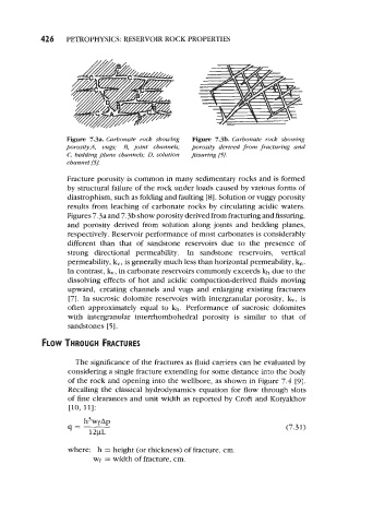
Figure 7.3% Carbonate rock showing Figure 7.3b. Carbonate rock showing
pomsity:A, vugs; B, joint channels; porosity derived f?om fracturing and
C, bedding plane channels; 0, solution fissuring [5].
cbanneZ [5J.
Fracture porosity is common in many sedimentary rocks and is formed
by structural failure of the rock under loads caused by various forms of
diastrophism, such as folding and faulting [8]. Solution or vuggy porosity
results from leaching of carbonate rocks by circulating acidic waters.
Figures 7.3a and 7.3b show porosity derived from fracturing and fissuring,
and porosity derived from solution along joints and bedding planes,
respectively. Reservoir performance of most carbonates is considerably
different than that of sandstone reservoirs due to the presence of
strong directional permeability. In sandstone reservoirs, vertical
permeability, k,, is generally much less than horizontal permeability, kn.
In contrast, k,, in carbonate reservoirs commonly exceeds kh due to the
dissolving effects of hot and acidic compaction-derived fluids moving
upward, creating channels and vugs and enlarging existing fractures
[7]. In sucrosic dolomite reservoirs with intergranular porosity, k,, is
often approximately equal to kh. Performance of sucrosic dolomites
with intergranular interrhornbohedral porosity is similar to that of
sandstones [ 51.
FLOW THROUGH FRACTURES
The significance of the fractures as fluid carriers can be evaluated by
considering a single fracture extending for some distance into the body
of the rock and opening into the wellbore, as shown in Figure 7.4 [9].
Recalling the classical hydrodynamics equation for flow through slots
of fine clearances and unit width as reported by Croft and Kotyakhov
[lo, 111:
h3wfAp
q= l2pL (7.31)
where: h = height (or thickness) of fracture, cm.
wf = width of fracture, cm.