
Page 102 - Photonics Essentials an introduction with experiments
P. 102
Photoconductivity
96 Photonic Devices
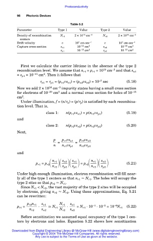
Table 5.2
Parameter Type 1 Value Type 2 Value
Density of recombination N r1 2 × 10 15 cm –3 N r2 2 × 10 16 cm –3
centers
7
7
Drift velocity v 10 cm-sec –1 v 10 cm-sec –1
Capture cross-section s n1 10 –15 cm 2 s n2 10 –20 cm 2
10 –15 cm 2 10 –15 cm 2
s p1 s p2
First we calculate the carrier lifetime in the absence of the type 2
recombination level. We assume that n r1 = p r1 = 10 15 cm –3 and that s n1
2
= s p1 = 10 –15 cm . Then it follows that
n1 = p1 = (p n1 vs n1 ) = (p n2 vs n2 ) = 10 –7 sec (5.18)
Now we add 2 × 10 16 cm –3 impurity states having a small cross section
2
for electrons of 10 –20 cm and a normal cross section for holes of 10 –15
cm .
2
Under illumination, f = (n/ n ) = (p/ p ) is satisfied by each recombina-
tion level. That is,
class 1: n(p r1 vs n1 ) = p(n r1 vs p1 ) (5.19)
and
class 2: n(p r2 vs n2 ) = p(n r2 vs p2 ) (5.20)
Next,
p p r1 vs n1 p r2 vs n2
= =
n n r1 vs p1 n r2 vs p2
and
p = p r2 = p r2 (5.21)
n r1
s n2
s n1
s n2
n r1
r1
n r2 s p2 s p1 n r2 s p2
Under high enough illumination, electron recombination will fill near-
ly all of the type 1 centers so that n r1 N r1 . The holes will occupy the
type 2 sites so that p r2 N r1 .
Since N r1 < N r2 , the vast majority of the type 2 sites will be occupied
by electrons, giving n r2 N r2 . Using these approximations, Eq. 5.21
can be rewritten:
p r2 n r1 s n1 N r1 s n1 –1 –5 –6
p r1 = · N r1 · = N r1 ·10 ·10 = 10 N r1 (5.22)
n r2 s n2 N r2 s n2
Before sensitization we assumed equal occupancy of the type 1 cen-
ters by electrons and holes. Equation 5.22 shows how sensitization
Downloaded from Digital Engineering Library @ McGraw-Hill (www.digitalengineeringlibrary.com)
Copyright © 2004 The McGraw-Hill Companies. All rights reserved.
Any use is subject to the Terms of Use as given at the website.