
Page 164 - Photonics Essentials an introduction with experiments
P. 164
Lasers
158 Photonic Devices
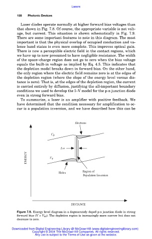
Laser diodes operate normally at higher forward bias voltages than
that shown in Fig. 7.8. Of course, the appropriate variable is not volt-
age, but current. This situation is shown schematically in Fig. 7.9.
There are some important features to note in this diagram. The most
important is that the physical overlap of occupied conduction and va-
lence band states is even more complete. This improves optical gain.
There is now a perceptible electric field in the contact regions, which
we have up to now presumed to have negligible resistance. The width
of the space–charge region does not go to zero when the bias voltage
equals the built-in voltage as implied by Eq. 4.5. This indicates that
the depletion model breaks down in forward bias. On the other hand,
the only region where the electric field remains zero is at the edges of
the depletion region (where the slope of the energy level versus dis-
tance is zero). That is, at the edges of the depletion region, the current
is carried entirely by diffusion, justifying the all-important boundary
conditions we used to develop the I–V model for the p-n junction diode
even in strong forward bias.
To summarize, a laser is an amplifier with positive feedback. We
have determined that the condition necessary for amplification to oc-
cur is a population inversion, and we have described how this can be
Electrons
C B
w
ENERGY V B
Region of
Holes
Population Inversion
DISTANCE
Figure 7.9. Energy level diagram in a degenerately doped p-n junction diode in strong
forward bias (V > V BI ). The depletion region is increasingly more narrow but does not
decrease to zero.
Downloaded from Digital Engineering Library @ McGraw-Hill (www.digitalengineeringlibrary.com)
Copyright © 2004 The McGraw-Hill Companies. All rights reserved.
Any use is subject to the Terms of Use as given at the website.