
Page 167 - Pipelines and Risers
P. 167
140 Chapter 10
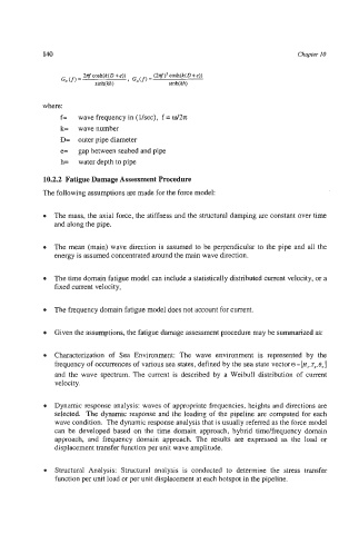
where:
f= wave frequency in (Usee), f = w/2n
k= wave number
D= outer pipe diameter
e= gap between seabed and pipe
h= water depth to pipe
10.2.2 Fatigue Damage Assessment Procedure
The following assumptions are made for the force model:
The mass, the axial force, the stiffness and the structural damping are constant over time
and along the pipe.
The mean (main) wave direction is assumed to be perpendicular to the pipe and all the
energy is assumed concentrated around the main wave direction.
The time domain fatigue model can include a statistically distributed current velocity, or a
fixed current velocity,
The frequency domain fatigue model does not account for current.
Given the assumptions, the fatigue damage assessment procedure may be summarized as:
Characterization of Sea Environment: The wave environment is represented by the
frequency of occurrences of various sea states, defined by the sea state vector8=[H,,Tp,e,]
and the wave spectrum. The current is described by a Weibull distribution of current
velocity.
Dynamic response analysis: waves of appropriate frequencies, heights and directions are
selected. The dynamic response and the loading of the pipeline are computed for each
wave condition. The dynamic response analysis that is usually referred as the force model
can be developed based on the time domain approach, hybrid time/frequency domain
approach, and frequency domain approach. The results are expressed as the load or
displacement transfer function per unit wave amplitude.
Structural Analysis: Structural analysis is conducted to determine the stress transfer
function per unit load or per unit displacement at each hotspot in the pipeline.