
Page 198 - Pipelines and Risers
P. 198
Trawl Impact, Pullover and Hooking Loads 171
(i.e. significantly less than for the flat seabed examples) due to the release of thermal and
pressure strain into the lateral buckle. A friction factor of 0.3 has been applied.
: 25
-306
-- 23
Seabed Profile --
-308 21
-- 19
Node 6227 -. 17
-310 -- 15
-
A
E
5 -312
--7 -I
-- 5
1 1
-316 I t -- 3
1
.318
-3
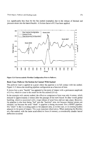
Figure 11.4 Uneven seabed: Flowline Confguration Prior to pullover.
Basic Case: Pullover On Setion In Contact With Seabed
The pullover load is applied at a point where the pipeline is in full contact with the seabed.
Figure 11.5 shows the resulting pipeline configuration as a function of time.
It shows how a new “buckle” has appeared at the point of impact with a permanent amplitude
of 2.4 m, which is close to the result for the flat seabed (2.8 m).
In the example with uneven seabed, the effective compressive force was only 4 tonnes, which
reduced to approximately 2 tonnes after the passage of the trawl board. In other words global
buckling, which is associated with a large release of axial force did not take place. However,
the pipeline is also here being “fed” into the “buckled” area, not because thermal strains are
released, but because the axial “slack” in pipeline is being recovered. For a HP/H” pipeline,
this “slack” is due to existing spans in the adjacent area, as in this case, or in existing buckles
adjacent to the point of impact. This is an important observation; When analysing the flowline
on a flat seabed, with the same axial effective force (4 tonnes), a considerably smaller lateral
deflection occurred.