
Page 94 - Pipelines and Risers
P. 94
Limit-state based Strength Design 67
4.4 Local BucklinglCollapse
This section is based on Hauch and Bai (1999).
Local Buckling
For pipelines subjected to combined pressure, longitudinal force and bending, local buckling
may occur. The failure mode may be yielding of the cross section or buckling on the
compressive side of the pipe. The criteria given in this guideline may be used to calculate the
maximum allowable bending moment for a given scenario. It shall be noted that the maximum
allowable bending moment given in this guideline does not take fracture into account and that
fracture criteria therefore may reduce the bending capacity of the pipe. This particularly
applies for high-tensionhigh-pressure load conditions.
Load Versus Displacement Controlled Situations
The local buckling check can be separated into a check for load controlled situations (bending
moment) and one for displacement controlled situations (strain level). Due to the relation
between applied bending moment and maximum strain in a pipe, a higher allowable strength
for a given target safety level can be achieved by using a strain-based criterion than the
bending moment criterion. Consequently the bending moment criterion can, conservatively be
used for both load and displacement controlled situations. In this guideline only the bending
moment criterion is given.
Local Buckling and Accumulated Out-of-Roundness
Increased out-of-roundness due to installation and cyclic operating loads may aggravate local
buckling and is to be considered. It is recommended that out-of-roundness due to through life
loads be simulated using finite element analysis.
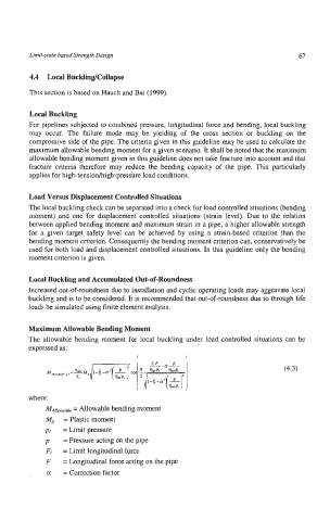
Maximum Allowable Bending Moment
The allowable bending moment for local buckling under load controlled situations can be
expressed as:
I \
(4.3)
where:
MAllowable = Allowable bending moment
Mp = Plastic moment
pL = Limit pressure
p = Pressure acting on the pipe
Fl = Limit longitudinal force
F = bngitudinal force acting on the pipe
a! = Correction factor