
Page 141 - Planning and Design of Airports
P. 141
110 Airp o r t Pl anning
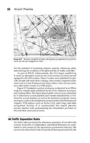
FIGURE 3-7 Airways, navigational aids, and airports as depicted on an IFR en
route low altitude navigational chart.
has the potential of increasing airspace capacity, enhancing safety,
and reducing the workload of the pilot and the air traffic controller.
As part of RNAV enhancements, the FAA began establishing
T-routes as alternative routes to the victor airways for those aircraft
equipped with GPS systems. These T-routes were established to pro-
vide aircraft with more direct routing, often around congested traffic
areas such as Class B airspace and areas where victor airways inter-
sect, often in the vicinity of a VOR station.
Figure 3-7 illustrates a portion of airspace as depicted in an IFR en
route low altitude chart, published by the FAA’s National Aeronauti-
cal Charting Office. This figure depicts both victor airways (identified
by V followed by a route number) and T-routes (identified by a T fol-
lowed by a route number), as well as the locations of airports, classes
of airspace (such as the shaded area around Jacksonville International
Airport), VOR stations (such as Taylor, Cecil, and Craig), and other
navigational facilities. It is recommended that airport planners
become familiar with understanding the information provided on
this and other aeronautical charts.
Air Traffic Separation Rules
Air traffic rules governing the minimum separation of aircraft in the
vertical, horizontal or longitudinal, and lateral directions are estab-
lished in each country by the appropriate government authority. The
current rules described in this text are those that are prescribed by the