
Page 210 - Planning and Design of Airports
P. 210
Geometric Design of the Airfield 175
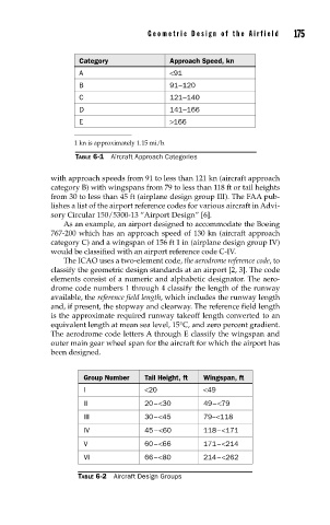
Category Approach Speed, kn
A <91
B 91 –120
C 121 –140
D 141 –166
E >166
1 kn is approximately 1.15 mi/h
TABLE 6-1 Aircraft Approach Categories
with approach speeds from 91 to less than 121 kn (aircraft approach
category B) with wingspans from 79 to less than 118 ft or tail heights
from 30 to less than 45 ft (airplane design group III). The FAA pub-
lishes a list of the airport reference codes for various aircraft in Advi-
sory Circular 150/5300-13 “Airport Design” [6].
As an example, an airport designed to accommodate the Boeing
767-200 which has an approach speed of 130 kn (aircraft approach
category C) and a wingspan of 156 ft 1 in (airplane design group IV)
would be classified with an airport reference code C-IV.
The ICAO uses a two-element code, the aerodrome reference code, to
classify the geometric design standards at an airport [2, 3]. The code
elements consist of a numeric and alphabetic designator. The aero-
drome code numbers 1 through 4 classify the length of the runway
available, the reference field length, which includes the runway length
and, if present, the stopway and clearway. The reference field length
is the approximate required runway takeoff length converted to an
equivalent length at mean sea level, 15°C, and zero percent gradient.
The aerodrome code letters A through E classify the wingspan and
outer main gear wheel span for the aircraft for which the airport has
been designed.
Group Number Tail Height, ft Wingspan, ft
I <20 <49
II 20 – <30 49 – <79
III 30 – <45 79 –<118
IV 45 –<60 118 – <171
V 60 – <66 171 – <214
VI 66 – <80 214 – <262
TABLE 6-2 Aircraft Design Groups