
Page 345 - Planning and Design of Airports
P. 345
Airport Lighting, Marking, and Signage 303
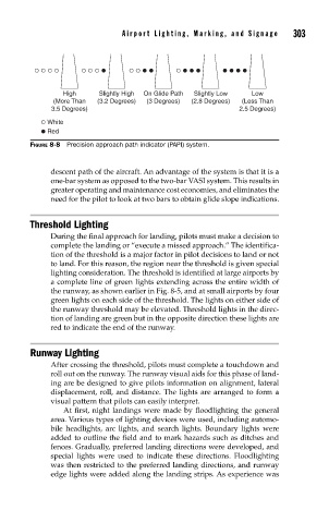
High Slightly High On Glide Path Slightly Low Low
(More Than (3.2 Degrees) (3 Degrees) (2.8 Degrees) (Less Than
3.5 Degrees) 2.5 Degrees)
White
Red
FIGURE 8-8 Precision approach path indicator (PAPI) system.
descent path of the aircraft. An advantage of the system is that it is a
one-bar system as opposed to the two-bar VASI system. This results in
greater operating and maintenance cost economies, and eliminates the
need for the pilot to look at two bars to obtain glide slope indications.
Threshold Lighting
During the final approach for landing, pilots must make a decision to
complete the landing or “execute a missed approach.” The identifica-
tion of the threshold is a major factor in pilot decisions to land or not
to land. For this reason, the region near the threshold is given special
lighting consideration. The threshold is identified at large airports by
a complete line of green lights extending across the entire width of
the runway, as shown earlier in Fig. 8-5, and at small airports by four
green lights on each side of the threshold. The lights on either side of
the runway threshold may be elevated. Threshold lights in the direc-
tion of landing are green but in the opposite direction these lights are
red to indicate the end of the runway.
Runway Lighting
After crossing the threshold, pilots must complete a touchdown and
roll out on the runway. The runway visual aids for this phase of land-
ing are be designed to give pilots information on alignment, lateral
displacement, roll, and distance. The lights are arranged to form a
visual pattern that pilots can easily interpret.
At first, night landings were made by floodlighting the general
area. Various types of lighting devices were used, including automo-
bile headlights, arc lights, and search lights. Boundary lights were
added to outline the field and to mark hazards such as ditches and
fences. Gradually, preferred landing directions were developed, and
special lights were used to indicate these directions. Floodlighting
was then restricted to the preferred landing directions, and runway
edge lights were added along the landing strips. As experience was