
Page 401 - Planning and Design of Airports
P. 401
350 Airp o r t D e sign
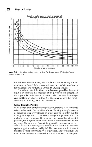
FIGURE 9-4 Intensity-duration rainfall pattern for design storm (Federal Aviation
Administration [2] ).
for drainage areas tributary to drain line A, shown in Fig. 9-5, are
tabulated in Table 9-2. It is assumed that the coefficients of runoff
for pavement and for turf are 0.90 and 0.30, respectively.
From these data, inlet times have been computed by the use of
Fig. 9-3 on the basis that the slope of the pavement is 1 percent and
the slope of the turfed area is 1.5 percent. The inlet times for this spe-
cific problem are shown in Fig. 9-3. The computations for runoff,
assuming no ponding, are shown in Table 9-3.
Typical Example—Ponding
In the design of an airfield drainage system, ponding may be used to
effect a reduction in the cost of installation. Ponding is simply a means
of providing temporary storage of runoff prior to its entry into the
underground system. For purposes of design computation, the pon-
ded volume may be assumed to be an inverted pyramid or a truncated
pyramid, the height of which is the depth of water above the inlet at
any stage. The area of the base of the pyramid is taken as the surface
area of the pond. If ponding were permitted, the layout of the drainage
system might be as shown in Fig. 9-6. The most remote point to one of
the inlets is 950 ft, comprising 100 ft of pavement and 850 ft of turf. The
time of concentration is estimated at 4 + 54 = 58 min. The complete