
Page 89 - Plastics Engineering
P. 89
72 Mechanical Behaviour of Plastics
set of design curves are developed to show how the different combinations of
dimensions might be selected.
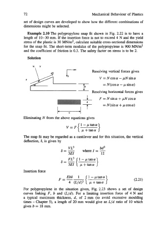
Example 2.10 The polypropylene snap fit shown in Fig. 2.22 is to have a
length of 10-30 mm. If the insertion force is not to exceed 4 N and the yield
stress of the plastic is 30 MN/m2, calculate suitable cross-sectional dimensions
for the snap fit. The short-term modulus of the polypropylene is 900 MN/m2
and the coefficient of friction is 0.3. The safety factor on stress is to be 2.
Solution
Resolving vertical forces gives
V=Ncosa-pNsina
= N(cos a - p sin a)
Resolving horizontal forces gives
1 F=Nsina+pNcosa
= N(sina + pcosa)
b
Eliminating N from the above equations gives
V=F{ 1-ptana }
p+tana
The snap fit may be regarded as a cantilever and for this situation, the vertical
deflection, ti, is given by
VL3 bd3
ti=- 3EI where I = -
12
ti=-{ FL3 1-ptana }
3EI p + tana
Insertion force
F=-- (Lfd)l { :-:E:} (2.21)
For polypropylene in the situation given, Fig. 2.23 shows a set of design
curves linking F, b and (L/d). For a limiting insertion force of 4 N and
a typical maximum thickness, d, of 2 mm (to avoid excessive moulding
times - Chapter 5). a length of 20 mm would give an L/d ratio of 10 which
gives b = 18 mm.