
Page 345 - Power Electronic Control in Electrical Systems
P. 345
//SYS21/F:/PEC/REVISES_10-11-01/075065126-CH008.3D ± 331 ± [290±372/83] 17.11.2001 10:29AM
Power electronic control in electrical systems 331
STATCOM (FACTS controller), with the active power flow controlled by the angle
between the AC system and VSC voltages and the reactive power flow controlled by
the difference between the magnitudes of these voltages. As with the STATCOM, the
capacitor acts as the energy storage device and its size is chosen based on power
ratings, control and harmonics considerations. The D-STATCOM controller con-
tinuously monitors the load voltages and currents and determines the amount of
compensation required by the AC system for a variety of disturbances. In this
section, the D-STATCOM is modelled using the digital simulator PSCAD/EMTDC.
Figure 8.48 shows the schematic diagram of the test system used to carry out the
transient modelling and analysis of the D-STATCOM. The test system comprises of a
230 kV three-phase transmission system, represented by a The  venin equivalent feeding
into the primary side of a three-winding transformer. A varying load is connected into
the 11 kV, secondary side of the transformer. A two-level VSC-based D-STATCOM is
connected to the 11 kV tertiary winding to provide instantaneous voltage support at
the load point. A 750 mF capacitor on the DC side provides the D-STATCOM energy
storage capabilities. Breaker Brk1 is used to control the period of operation of the
D-STATCOM and Brk2 controls the connection of Load 2 to the system.
In this particular example the aim of the D-STATCOM is to provide voltage
regulation at the load point and mitigate the voltage sag generated when the load
is increased. The system is considered to be operating under balanced conditions and
both loads are linear. The D-STATCOM structure is based on a simple two-level
VSC which is controlled using conventional sinusoidal PWM. Filtering equipment is
not included in the design.
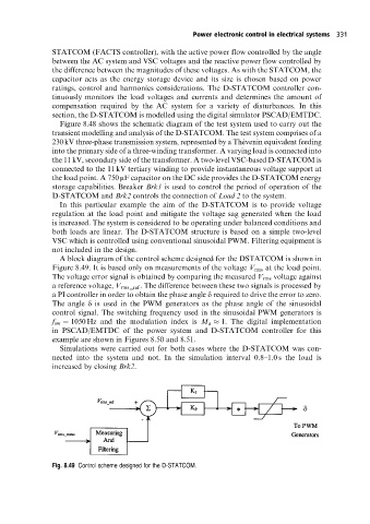
A block diagram of the control scheme designed for the DSTATCOM is shown in
Figure 8.49. It is based only on measurements of the voltage V rms at the load point.
The voltage error signal is obtained by comparing the measured V rms voltage against
a reference voltage, V rms _ ref . The difference between these two signals is processed by
a PI controller in order to obtain the phase angle d required to drive the error to zero.
The angle d is used in the PWM generators as the phase angle of the sinusoidal
control signal. The switching frequency used in the sinusoidal PWM generators is
f sw 1050 Hz and the modulation index is M a 1. The digital implementation
in PSCAD/EMTDC of the power system and D-STATCOM controller for this
example are shown in Figures 8.50 and 8.51.
Simulations were carried out for both cases where the D-STATCOM was con-
nected into the system and not. In the simulation interval 0.8±1.0 s the load is
increased by closing Brk2.
Fig. 8.49 Control scheme designed for the D-STATCOM.