
Page 148 - Power Electronics Handbook
P. 148
D.C. line control 141
(C)
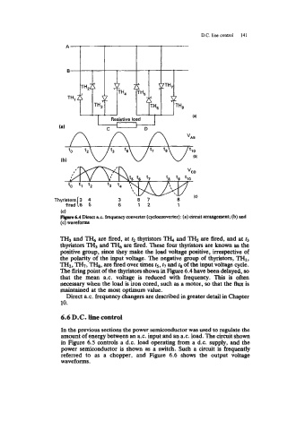
Prprc 6.4 Direct a.c. frequency converter (cydoconverter): (a) circuit arrangement; (b) and
(c) waveforms
TH3 and TH, are fired, at r2 thyristors TH, and TH5 are fired, and at r3
thyristors TH3 and are fired. These four thyristors are known as the
positive group, since they make the load voltage positive, irrespective of
the polarity of the input voltage. The negative group of thyristors, TH1,
TH2, TH,, m, are fired over times rs, r7 and r8 of the input voltage cycle.
The firing point of the thyristors shown in Figure 6.4 have been delayed, so
that the mean a.c. voltage is reduced with frequency. This is often
necessary when the load is iron cored, such as a motor, so that the flux is
maintained at the most optimum value.
Direct 8.c. frequency changers are described in greater detail in Chapter
10.
6.6 D.C. he control
In the previous sections the power semiconductor was used to regulate the
amount of energy between an a.c. input and an ax. load. The circuit shown
in Figure 6.5 controls a d.c. load operating from a d.c. supply, and the
power semiconductor is shown as a switch. Such a circuit is frequently
referred to as a chopper, and Figure 6.6 shows the output voltage
waveforms.