
Page 258 - Power Electronics Handbook
P. 258
248 Forced commutation techniques
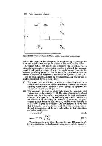
Flgnre 11.5 Modification to Figure 11.3 by the addition of capacitor resonant charge
before. The capacitor then charges to the supply voltage V, through the
load, and thyristor TH, will go off as soon as this has been completed.
Equations (11.1) and (11.2) still determine the conditions for a
successful commutation, but since the capacitor is charged via a resonant
circuit it will reach a voltage of twice the supply voltage, losses in the
resonant path being ignored, so that the size of the commutation capacitor
needed is now halved compared to the circuits of Figures 11.3 and 11.4.
The six-point checklist, given in the previous section, can now be used to
analyse the circuit shown in Figure 11.5:
(i) The circuit can be operated in either a variable-frequency or a
variable mark-space mode, since commutation does not start until an
auxiliary commutation thyristor is fired, giving the operator full
control over the on and off periods.
(ii) The minimum on time re, which determines the minimum load
voltage, is given by equation (11.3). The value of capacitor C is fixed
by the need for a successful commutation at the peak load current
expected, as in equation (ll.l), so the only way in which this time can
be reduced is by decreasing the inductor L1. However, the peak
current through thyristors THI and TH3, caused by the charging of
capacitor C, is given by equation (11.4), and from this it can be seen
that if inductor L1 is made too small then the charging current
through these devices will be very high, adding to their dissipation
and rating requirements.
rc = Jc J(L1C) (11.3)
(11.4)
The minimum time for which the main thyristor TH1 must be off
(r,,) is dependent on the load current, being longer on light loads, if it