
Page 91 - Practical Control Engineering a Guide for Engineers, Managers, and Practitioners
P. 91
&& C~apter T~ree
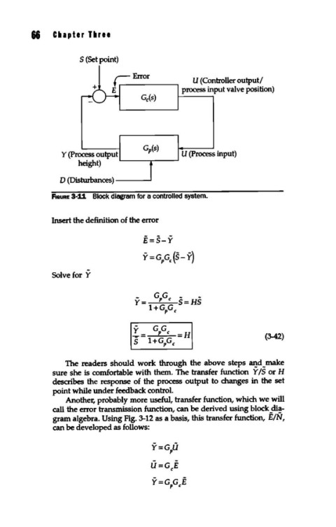
S (Set point)
U (Controller output/
process input valve position)
Gp(s)
Y (Process output U (Process input)
height) L-----r----'
D (Disturbances) __ __,
F1auRE 3-11 Block diagram for a controlled system.
Insert the definition of the error
E=s-¥
Y=GPG,(s- ¥)
Solve for Y
(3-42)
The readers should work through the above steps cu.!d _make
sure she is comfortable with them. The transfer function Y IS or H
describes the response of the process output to changes in the set
point while under feedback control.
Another, probably more useful, transfer function, which we will
call the error transmission function, can be derived using block _di!-
gram algebra. Using Fig. 3-12 as a basis, this transfer function, E/N,
can be developed as follows:
U=G,E
Y=GPG,E