
Page 350 - Practical Design Ships and Floating Structures
P. 350
325
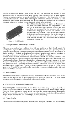
structure members(deck, bottom, inner bottom, side shell and bulkheads) are idealized by shell
elements in order to take into account lateral pressure loads and to resist out of plane bending.
Transverse structure members are also idealized by shell elements. The longitudinal stiffeners,
vertical stiffeners attached to trans. BHD and face plate of horizontal stringers are idealized by beam
elements in order to resist bending moment. The secondary structural members such as stiffeners on
floors and webs etc. are idealized by truss elements in order to reflect axial load.
Half of the sectional properties are applied for the elements in
,,- the center line plane of the model, fore end plane and aft end
m-3
plane of the model. Face plates and panel stiffeners of primary
members are represented by line elements with a cross
sectional area. The properties of curved face plate are defined
by considering effective areas. Corrosion margin is considered
in the definition of element properties. The number of mesh in
double bottom floor and double side web are 4, the number of
mesh between frames is 2 and the number of mesh between
longitudinal stiffeners is 1.
Figure 2: 3-D FE model
3.2 Loading Conditions and Boundary Conditions
The most severe realistic load conditions of the ship are considered for the 3-D tank analysis. To
investigate the response of the structure due to the local hydro-static and hydro-dynamic pressure, 8
load cases are considered. 5 cases are considered in sea-going condition and 3 cases are considered in
harbor condition. Realistic combinations of external and internal dynamic loads are considered in
sea-going conditions and the static loads are only considered in harbor conditions.
In order to consider shear force imbalance between downward loads and buoyancy, imbalance shear
forces are calculated in way of the transverse bulkheads at inside longi. BHD, inner skin and side shell.
To eliminate imbalanced shear forces, the calculated imbalance shear forces are re-acted to the same
locations. The final 3-D cargo tank analysis shows the sum of the imbalanced shear forces is about 0.
For symmetrical nature of geometry and loading conditions, symmetrical constraints are applied at the
centerline plane of the FE model. Symmetrical constraints are applied at the end of forward and aft
plane of the FE model. Vertical fixed boundary is applied at the top node at the intersection of forward
transverse BHD and side shell.
3.3 Analysis Results
Evaluation of stress results is performed by using element stress which is calculated at the middle
surface of plate bending element. According to the results, the newly designed VLCC is found to have
enough strength with regard to yielding criteria and structural stability.
4 EVALUATION OF FATIGUE STRENGTH
Fatigue strength has been considered as the one of main issues in the design of ship structure. That is,
typical structural joints should be designed to sustain design service life without fatigue damage.
Therefore, fatigue analyses for hopper knuckle connection and critical connections of longitudinals
have been performed to evaluate whether these structural connections of subject vessel have sufficient
fatigue strength in compliance with DNV's fatigue guidance[DNV, 19981.
4.1 Fatigue Loading
The only fluctuating loading components excluding static loading are considered as a fatigue loading,