
Page 97 - Practical Design Ships and Floating Structures
P. 97
12
I cl L I
Figure 7: Shape modification of the midship section
The midship section has been selected to demonstrate the different levels of priority in the generation
process of the hull shape. Every single parameter that is part of the vocabulary available in the model
has to be related to a set of rules embedded in the generation process.
4 EXAMPLE
To demonstrate the performance of the entire modelling approach, two different shape variations -
namely global and local modifications - are presented. The change of global parameters depicts the
capabilities of shape generation in the early design phase. Local changes of hydrodynamic relevance
have been selected to demonstrate the applicability of the modelling approach for automated shape
variation without shape deformation.
4.1 Variation of principle dimensions
At the early stage of preliminary design the appearance of the ship is specified and some of the
principle dimensions have to be initialised and, possibly, fixed. Typically, a subset of important
parameters suffices to capture the requirements resulting from the transportation task. The freedom for
shape variations is substantial and yet all desired geometric attributes are readily available in full detail.
Once the model-file is created with a limited set of parameters, a complete geometric description can
be created on demand. The values of parameters can be specified either in absolute terms or relative to
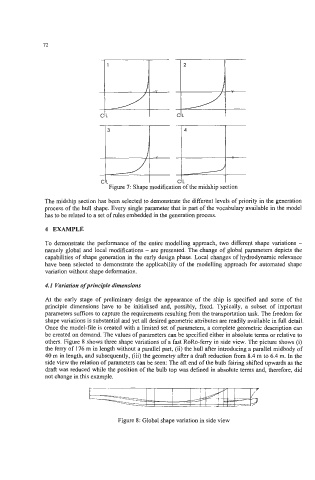
others. Figure 8 shows three shape variations of a fast RoRo-ferry in side view. The picture shows (i)
the ferry of 176 m in length without a parallel part, (ii) the hull after introducing a parallel midbody of
40 m in length, and subsequently, (iii) the geometry after a draft reduction from 8.4 m to 6.4 m. In the
side view the relation of parameters can be seen: The aft end of the bulb fairing shifted upwards as the
draft was reduced while the position of the bulb top was defined in absolute terms and, therefore, did
not change in this example.
Figure 8: Global shape variation in side view