
Page 195 - Practical Power System and Protective Relays Commissioning
P. 195
196 Practical Power System and Protective Relays Commissioning
At the end of the characteristic at a certain multiplication of the current
the time becomes DT (t 0 ).
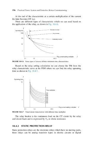
There are different types of characteristic which we can used based on
the application of the relay, as shown in Fig. 18.4.6.
FIGURE 18.4.6 Some types of inverse definite minimum time characteristics.
Based on the relay setting calculation we can choose the TM from the
relay characteristic curve at the PSM where we can find the relay operating
time as shown in Fig. 18.4.7.
FIGURE 18.4.7 Time/current characteristic with different time multiplier.
The relay burden is the continuous load on the CT circuit by the relay
and circuit leads and is expressed by V A or ohmic resistance.
18.4.2 STATIC PROTECTION RELAY
Static protection relays are the electronic relays which have no moving parts,
these relays can be analog transistor types in electric circuits or digital