
Page 247 - Practical Ship Design
P. 247
Powering I1 209
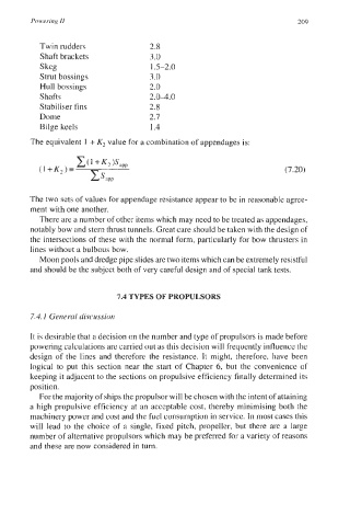
Twin rudders 2.8
Shaft brackets 3.0
Skeg 1.5-2.0
Strut bossings 3.0
Hull bossings 2.0
Shafts 2.04.0
Stabiliser fins 2.8
Dome 2.7
Bilge keels 1.4
The equivalent 1 + K2 value for a combination of appendages is:
(7.20)
The two sets of values for appendage resistance appear to be in reasonable agree-
ment with one another.
There are a number of other items which may need to be treated as appendages,
notably bow and stem thrust tunnels. Great care should be taken with the design of
the intersections of these with the normal form, particularly for bow thrusters in
lines without a bulbous bow.
Moon pools and dredge pipe slides are two items which can be extremely resistful
and should be the subject both of very careful design and of special tank tests.
7.4 TYPES OF PROPULSORS
7.4.1 General discussion
It is desirable that a decision on the number and type of propulsors is made before
powering calculations are carried out as this decision will frequently influence the
design of the lines and therefore the resistance. It might, therefore, have been
logical to put this section near the start of Chapter 6, but the convenience of
keeping it adjacent to the sections on propulsive efficiency finally determined its
position.
For the majority of ships the propulsor will be chosen with the intent of attaining
a high propulsive efficiency at an acceptable cost, thereby minimising both the
machinery power and cost and the fuel consumption in service. In most cases this
will lead to the choice of a single, fixed pitch, propeller, but there are a large
number of alternative propulsors which may be preferred for a variety of reasons
and these are now considered in turn.