
Page 347 - Practical Well Planning and Drilling Manual
P. 347
Section 3 revised 11/00/bc 1/17/01 12:00 PM Page 323
Well Control [ ]
3.1.5
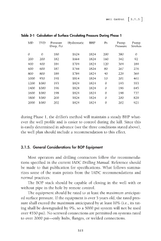
Table 3-1 Calculation of Surface Circulating Pressure During Phase 1
MD TVD Pressure Hydrostatic BHP Ps Pump Pump
Drop, Pci Pressure Strokes
0 0 180 1624 1824 200 380 0
200 200 182 1664 1824 160 342 92
400 400 184 1704 1824 120 304 184
600 600 187 1744 1824 80 267 276
800 800 189 1784 1824 40 229 369
1000 950 191 1814 1824 10 201 461
1200 1000 193 1824 1824 0 193 553
1400 1000 196 1824 1824 0 196 645
1600 1000 198 1824 1824 0 198 737
1800 1000 200 1824 1824 0 200 829
2000 1000 202 1824 1824 0 202 921
during Phase 1, the driller’s method will maintain a steady BHP what-
ever the well profile and is easier to control during the kill. Since this
is easily determined in advance (see the three conditions stated above),
the well plan should include a recommendation to this effect.
3.1.5. General Considerations for BOP Equipment
Most operators and drilling contractors follow the recommenda-
tions specified in the current IADC Drilling Manual. Reference should
be made to that publication for specifications. What follows summa-
rizes some of the main points from the IADC recommendations and
normal practices.
The BOP stack should be capable of closing in the well with or
without pipe in the hole by remote control.
The equipment should be rated to at least the maximum anticipat-
ed surface pressure. If the equipment is over 5 years old, the rated pres-
sure shall exceed the maximum anticipated by at least 10% (i.e., its rat-
ing shall be downgraded by 9%, so a 5000 psi system will not be used
over 4550 psi). No screwed connections are permitted on systems rated
to over 2000 psi—only hubs, flanges, or welded connections.
323