
Page 98 - Practical Well Planning and Drilling Manual
P. 98
Section 1 revised 11/00/bc 1/17/01 2:56 PM Page 74
[ ] Well Design
1.4.13
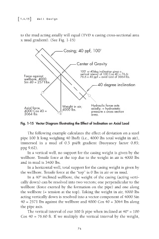
to the mud acting axially will equal (TVD x casing cross-sectional area
x mud gradient). (See Fig. 1-15)
Casing; 40 ppf, 100'
Center of Gravity
100' at 40deg inclination gives a
vertical interval of 100 Cos 40 = 76.6;
Force against 76.6 x 40 ppf = axial load of 3064 lbs.
wellbore, 4000
Sin 40 = 2571lbs.
40 degree inclination
Weight in air; Hydraulic force acts
Axial force, 4000 lbs. axially; = hydrostatic
4000 Cos 40 = pressure x cross section
3064 lbs area.
Fig. 1-15 Vector Diagram Illustrating the Effect of Inclination on Axial Load
The following example calculates the effect of deviation on a steel
pipe 100 ft long weighing 40 lbs/ft (i.e., 4000 lbs total weight in air),
immersed in a mud of 0.5 psi/ft gradient (buoyancy factor 0.85;
ppg 9.62).
In a vertical well, no support for the casing weight is given by the
wellbore. Tensile force at the top due to the weight in air is 4000 lbs
and in mud is 3400 lbs.
In a horizontal well, total support for the casing weight is given by
the wellbore. Tensile force at the “top” is 0 lbs in air or in mud.
In a 40° inclined wellbore, the weight of the casing (acting verti-
cally down) can be resolved into two vectors; one perpendicular to the
wellbore (force exerted by the formation on the pipe) and one along
the wellbore (= tension at the top). Taking the weight in air, 4000 lbs
acting vertically down is resolved into a vector component of 4000 Sin
40 = 2571 lbs against the wellbore and 4000 Cos 40 = 3064 lbs along
the pipe axis.
The vertical interval of our 100 ft pipe when inclined at 40° = 100
Cos 40 = 76.60 ft. If we multiply the vertical interval by the weight,
74