
Page 121 - Pressure Vessel Design Manual
P. 121
General Design 101
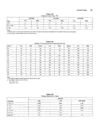
Table 2-22
Weights of Valve Trays, PSF
One Pass Two Pass Four Pass
Dia. C.S. Alloy C.S. Alloy C.S. Alloy
c 84" 13 11 14 12
I 84" to 180" I 12 I 10 I 13 I 11 I 15 i 13 i
I > 180" I 11.5 I 9.5 I 12.5 I 10.5 I 14.5 1 12.5 1
Notes:
1. Compute area on total cross-sectional area of vessel. The downcomer areas compensate for the weight of downcomers themselves.
2. Tray weights include weights of trays and downcomers.
Table 2-23
Weights of Tray Supports and Downcomer Bars (Ib)
ID (In.) C.S. Alloy ID (in.) C.S. Alloy ID (in.) C.S. Alloy
30 25 17 102 113 72 174 287 174
36 28 19 108 119 75 180 294 178
42 34 23 114 123 77 186 344 207
48 37 25 120 176 108 192 354 212
54 44 35 126 183 112 198 362 21 8
Notes:
1. Tray support weights include downcomer bolting bars as well.
2. Tray support ring sizes are as follows:
C.S.: 112" x 2% "
Alloy: 5/16' x 2% "
Diameter
Thickness < 150" > 150" Hemi-Heads
0.125" to 1" 0.0625 None 0.188
1" to 2" 0.125 0.25 0.375
2" to 3' 0.25 0.25 0.625
3" to 3.75' 0.375 0.375 0.75
3.75' to 4' 0.5 0.5 1
over 4.25" 0.75 0.75 1.5