Page 216 - Pressure Vessel Design Manual
P. 216

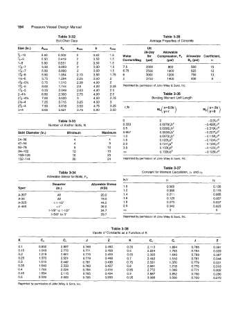
194    Pressure Vessel Design Manual

                              Table 3-32                                            Table 3-35
                             Bolt Chair Data                                 Average Properties of  Concrete

                                                                            Ult
                                                                          2&Day     Allowable
          3/4-10      5.50     0.302    2       3.50     1.5   Water        Str   Compression, Fc  Allowable  Coefficient,
          23-9        5.50     0.41 9   2       3.50     1.5   ContentlBag   (psi)    (Psi)      6, (Psi)    n
          1-8         5.50     0.551    2       3.50     1.5
          1%-7        5.50     0.693    2       3.50     1.5   7.5         2000       800         500       15
          1%-7        5.50     0.890    2       3.50     1.5   6.75        2500       1000        625       12
          15-6        5.50     1 .OM    2.13    3.50     1.75   6          3000       1200        750       10
          1 %-6       5.75     1.294    2.25    3.50     2     5           3750       1400        938        8
          1 %-5W      5.75     1.515    2.38    4.00     2
          1 3/4-5     6.00     1.744    2.5     4.00     2.25   Reprinted by permission of John Wiley & Sons, Inc.
          1  %-5      6.25     2.049    2.63    4.00     2.5
          24%         6.50     2.300    2.75    4.00     2.5                        Table 3-36
          2%4%        7.00     3.020    3       4.50     2.75                 Bending Moment Unit Length
          2%4         7.25     3.715    3.25    4.50     3
          23/44       7.50     4.61 8   3.50    4.75     3.25
          3-4         8.00     5.621    3.75    5.00     3.50


                              Table 3-33                       0                  0                        -o.5fce2
                         Number of Anchor Bolts, N              0.333             0.0078fcb2             -o.428fce2
                                                                0.5               0.0293f,b2             -0.319fc12
          Skirt Diameter (in.)     Minimum           Maximum   0.667              0.0558fcb2             -o.227fce2
                                                                1  .o             0.0972fcb2             -0.1  1  wCe2
          24-36                       4                 4       1.5               0.1 23fcb2             -o.i24fce2
          42-54                       4                 8       2.0               0.1 31fcb'             -0.1 25fce2
          60-78                        8                12      3.0               0.133fcb2              -0.1  25fce2
          84-1  02                    12                16      03                0.1 33fcb2             -o.i25fCe2
          108-1 26                    16               20
          132-1 44                    20               24       Reprinted by permission of John Wiley & Sons, Inc.

                                                                                    Table 3-37
                               Table 3-34                                Constant for Moment Calculation, y, and y2
                         Allowable Stress for Bolts, F,
                                                                ble                  Y1                      Y2
                           Diameter            Allowable Stress   1 .o
          spec               (in.)                  (KSV                              0.565                   0.135
                                                                1.2                   0.350                   0.1 15
          A-307               All                   20.0        1.4                   0.21 1                 0.085
          A-36                All                   19.0        1.6                   0.125                   0.057
          A-325             < 1-1f2"                44.0        1.8                   0.073                   0.037
          A-449              < 1"                   39.6        2.0                   0.042                   0.023
                         1-1f8" to 1-112"           34.7        co                     0                       0
                           1-518" to 3"             29.7
                                                                Reprinted by permission of John Wiley & Sons, Inc.

                                                         Table 3-38
                                                Values of Constants as a Function of  K

          K           cc         G           J          z          K         C,         c,          J          z
          0.1       0.852       2.887      0.766      0.480       0.55      2.113      1.884      0.785       0.381
          0.15       1.049      2.772      0.771      0.469       0.6       2.224      1.765      0.784       0.369
          0.2        1.21 8     2.661      0.776      0.459       0.65      2.333      1.640      0.783       0.357
          0.25       1.370      2.551      0.779      0.448      0.7        2.442      1.510      0.781       0.344
          0.3        1.510      2.442      0.781      0.438      0.75       2.551      1.370      0.779       0.331
          0.35       1.640      2.333      0.783      0.427       0.8       2.661      1.218      0.776       0.316
          0.4       1.765       2.224      0.784      0.416      0.85       2.772      1.049      0.771       0.302
          0.45       1.884      2.1 13     0.785      0.404       0.9       2.887      0.852      0.766       0.286
          0.5       2.000       2.000      0.785      0.393      0.95       3.008      0.600      0.760       0.270
          Reprinted by permission of John Wiley & Sons, Inc.
   211   212   213   214   215   216   217   218   219   220   221