
Page 123 - Primer on Enhanced Oil Recovery
P. 123
Gas flooding 113
recovery occurs due to an increase in the viscosity of the gas as a result of enrich-
ment with intermediate hydrocarbons and a resultant decrease in the ratio of mobility
of oil and gas.
Enriched with intermediate hydrocarbons (C3 C6), primarily propane, is often
injected into the formation. Moreover, due to the fact that the concentration of
intermediate hydrocarbons in a gas is higher than in oil, they begin to dissolve in
oil, which leads to oil swelling and a decrease in viscosity. As a result, oil recovery
significantly increases.
Liquefied gas injection started in the early 1950s. Numerous field tests and sev-
eral full-scale implementations using liquefied petroleum gas were carried out in
the USA for mixing displacement. However, the need for excessively large portions
of liquefied petroleum gas and the high market value of liquid propane made the
injection of liquefied petroleum gas economically unattractive. In this regard, to
reduce the cost of the technology has been later modified.
A small slug of liquefied petroleum gas is injected into the formation, which
forms a transition zone between the gas slug and oil. Usually, propane or its mix-
tures with other intermediate hydrocarbons are used as a slug of liquefied gas. The
displacement becomes miscible. The main advantage of this method is the absence
of capillary forces that prevent enhanced oil recovery when using immiscible meth-
ods. The efficiency of oil displacement this way increases significantly.
Injection pressure should ensure the maintenance of liquefied gas in a liquid
state, complete miscibility of a liquefied gas, both with oil and with a dry propul-
sion gas. At the same time, the required mixing pressure is significantly lower than
when injecting just dry or enriched gas. The need to maintain the liquefied gas in
the liquid state limits the application of the method to deposits with a temperature
below the critical for the gas used. For instance, the critical temperature for pure
0
propane is 96.6 С, and liquefied propane cannot be used at higher temperatures.
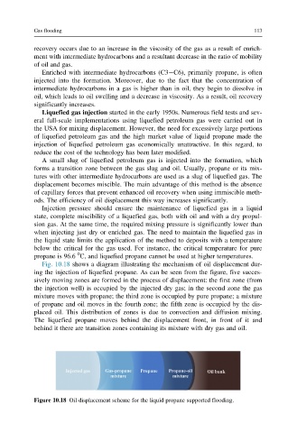
Fig. 10.18 shows a diagram illustrating the mechanism of oil displacement dur-
ing the injection of liquefied propane. As can be seen from the figure, five succes-
sively moving zones are formed in the process of displacement: the first zone (from
the injection well) is occupied by the injected dry gas; in the second zone the gas
mixture moves with propane; the third zone is occupied by pure propane; a mixture
of propane and oil moves in the fourth zone; the fifth zone is occupied by the dis-
placed oil. This distribution of zones is due to convection and diffusion mixing.
The liquefied propane moves behind the displacement front, in front of it and
behind it there are transition zones containing its mixture with dry gas and oil.
Figure 10.18 Oil displacement scheme for the liquid propane supported flooding.