
Page 64 - Primer on Enhanced Oil Recovery
P. 64
Oil recovery stages and methods 55
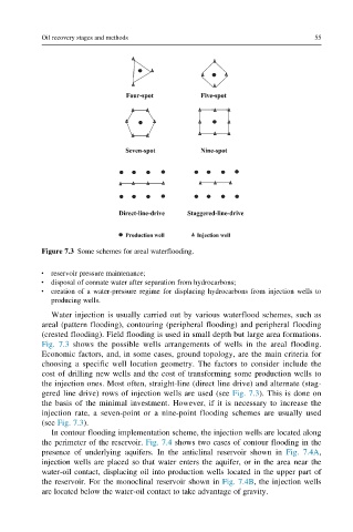
Figure 7.3 Some schemes for areal waterflooding.
reservoir pressure maintenance;
disposal of connate water after separation from hydrocarbons;
creation of a water-pressure regime for displacing hydrocarbons from injection wells to
producing wells.
Water injection is usually carried out by various waterflood schemes, such as
areal (pattern flooding), contouring (peripheral flooding) and peripheral flooding
(crested flooding). Field flooding is used in small depth but large area formations.
Fig. 7.3 shows the possible wells arrangements of wells in the areal flooding.
Economic factors, and, in some cases, ground topology, are the main criteria for
choosing a specific well location geometry. The factors to consider include the
cost of drilling new wells and the cost of transforming some production wells to
the injection ones. Most often, straight-line (direct line drive) and alternate (stag-
gered line drive) rows of injection wells are used (see Fig. 7.3). This is done on
the basis of the minimal investment. However, if it is necessary to increase the
injection rate, a seven-point or a nine-point flooding schemes are usually used
(see Fig. 7.3).
In contour flooding implementation scheme, the injection wells are located along
the perimeter of the reservoir. Fig. 7.4 shows two cases of contour flooding in the
presence of underlying aquifers. In the anticlinal reservoir shown in Fig. 7.4A,
injection wells are placed so that water enters the aquifer, or in the area near the
water-oil contact, displacing oil into production wells located in the upper part of
the reservoir. For the monoclinal reservoir shown in Fig. 7.4B, the injection wells
are located below the water-oil contact to take advantage of gravity.