
Page 311 - Process Equipment and Plant Design Principles and Practices by Subhabrata Ray Gargi Das
P. 311
11.4 Fractionator 313
(A) V top
Partial
Stage 1 Condenser
R = L 1 /(V top + L top )
L 1
Stage 2 L top
(B)
Stage N P1 P 1
Stage j–1
F 1 Stage N F1
Z F1
Stage N P2
P 2
V L
j, j–1,
L,j–1
H H
v,j
F 2 Stage N F2
Z F2
Stage j
Stage N–1 L
j ,
V j+1,
v,j+1 L,j
H H
V N
Stage N
B
Reboiler
(C) (D)
Stage N F –1
Stage N –1
P
–1
L ,
N F
L,N –1
H
F
F V NF V N L N –1 ,
P P
H V,FNF
H , N –1
F N
L
H V,N P
F
P
Z N
F
F L NF
H
L,FNF
Stage N
P
W
V i,N –1 , N P
P
V N
F
H V,N –1
H V,NF
P
Stage N F
L N
P
, H L ,N P
V N
L N ,
F
H V,N –1
F H L,N F
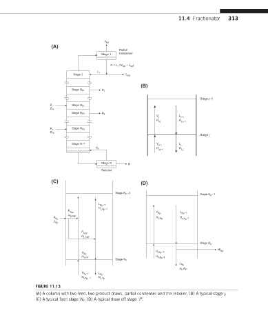
FIGURE 11.13
(A) A column with two feed, two product draws, partial condenser and the reboiler, (B) A typical stage j,
(C) A typical feed stage N F, (D) A typical draw off stage ‘P’.