
Page 50 -
P. 50
32 2 Process Modeling and Analysis
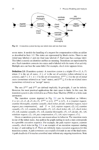
Fig. 2.1 A transition system having one initial state and one final state
seven states. It models the handling of a request for compensation within an airline
as described in Sect. 1.2. The states are represented by black circles. There is one
initial state labeled s1 and one final state labeled s7. Each state has a unique label.
This label is merely an identifier and has no meaning. Transitions are represented by
arcs. Each transition connects two states and is labeled with the name of an activity.
Multiple arcs can bear the same label. For example, check ticket appears twice.
Definition 2.1 (Transition system) A transition system is a triplet TS = (S,A,T )
where S is the set of states, A ⊆ A is the set of activities (often referred to as
actions), and T ⊆ S × A × S is the set of transitions. S start ⊆ S is the set of initial
states (sometimes referred to as “start” states), and S end ⊆ S is the set of final states
(sometimes referred to as “accept” states).
The sets S start and S end are defined implicitly. In principle, S can be infinite.
However, for most practical applications the state space is finite. In this case, the
transition system is also referred to as a Finite-State Machine (FSM) or a finite-state
automaton.
The transition system depicted in Fig. 2.1 can be formalized as follows:
S ={s1,s2,s3,s4,s5,s6,s7}, S start ={s1}, S end ={s7}, A ={register request,
examine thoroughly,examine casually,check ticket,decide,reinitiate request,reject
request,pay compensation}, and T ={(s1,register request,s2),(s2,examine
casually,s3), (s2,examine thoroughly,s3), (s2,check ticket,s4), (s3,check ticket,
s5),(s4,examine casually,s5), (s4,examine thoroughly,s5), (s5,decide,s6), (s6,
reinitiate request,s2), (s6,pay compensation,s7), (s6,reject request,s7)}.
Given a transition system one can reason about its behavior. The transition starts
in one of the initial states. Any path in the graph starting in such a state corresponds
to a possible execution sequence. For example, the path register request, examine
casually, check ticket in Fig. 2.1 is an example of an execution sequence starting
in state s1 and ending in s5. There are infinitely many execution sequences for this
transition system. A path terminates successfully if it ends in one of the final states.
A path deadlocks if it reaches a nonfinal state without any outgoing transitions. Note