
Page 183 - Programming Microcontrollers in C
P. 183
168 Chapter 4 Small 8-Bit Systems
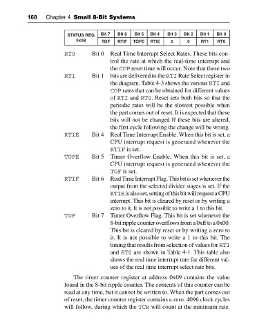
STATUS REG Bit 7 Bit 6 Bit 5 Bit 4 Bit 3 Bit 2 Bit 1 Bit 0
0x08 TOF RTIF TOFE RTIE 0 0 RT1 RT0
RT0 Bit 0 Real Time Interrupt Select Rates. These bits con
trol the rate at which the real-time interrupt and
the COP reset time will occur. Note that these two
RT1 Bit 1 bits are delivered to the RTI Rate Select register in
the diagram. Table 4-3 shows the various RTI and
COP rates that can be obtained for different values
of RTI and RT0. Reset sets both bits so that the
periodic rates will be the slowest possible when
the part comes out of reset. It is expected that these
bits will not be changed If these bits are altered,
the first cycle following the change will be wrong.
RTIE Bit 4 Real Time Interrupt Enable. When this bit is set, a
CPU interrupt request is generated whenever the
RTIF is set.
TOFE Bit 5 Timer Overflow Enable. When this bit is set, a
CPU interrupt request is generated whenever the
TOF is set.
RTIF Bit 6 Real Time Interrupt Flag. This bit is set whenever the
output from the selected divider stages is set. If the
RTIEis also set, setting of this bit will request a CPU
interrupt. This bit is cleared by reset or by writing a
zero to it. It is not possible to write a 1 to this bit.
TOF Bit 7 Timer Overflow Flag. This bit is set whenever the
8-bit ripple counter overflows from a 0xff to a 0x00.
This bit is cleared by reset or by writing a zero to
it. It is not possible to write a 1 to this bit. The
timing that results from selection of values for RT1
and RT0 are shown in Table 4-1. This table also
shows the real time interrupt rate for different val
ues of the real time interrupt select rate bits.
The timer counter register at address 0x09 contains the value
found in the 8-bit ripple counter. The contents of this counter can be
read at any time, but it cannot be written to. When the part comes out
of reset, the timer counter register contains a zero. 4096 clock cycles
will follow, during which the TCR will count at the minimum rate.