
Page 221 - Programming Microcontrollers in C
P. 221
206 Chapter 4 Small 8-Bit Systems
period. The way that this routine works, it is possible for an interrupt
to occur as a result of a compare on output compare 2. This interrupt
is to be ignored, and the first five lines of the code below tests for this
condition and clears interrupt when it occurs. This interrupt occurs
at the end of the on time. Control of the program must be out of this
portion of the ISR and in the main line code before the next interrupt
caused by OCF1 occurs. The time required for the first five lines of
code here is about 18 microseconds, which is the minimum on time.
void __TIMER_OC(void)
{
if(TSR.OCF2==1)
{
ac=OCLO2; /* if interrupt is caused by out
put*/
return; /* compare 2 reset it and return */
}
time_cnt.b.hi=TCHI; /* get in the TCR */
time_cnt.b.lo=TCLO; /* get lo byte */
time_cnt.l +=count; /* bump the time counter
for next*/
OCHI1=time_cnt.b.hi;/* interrupt */
OCLO1=time_cnt.b.lo;/* reset the OCF */
if(flag.PWM==1)
{
TCR.OLVL2=1;/* Timer Compare 2 to set output */
TCR.FOLV2=1;/* turn on Timer compare 2 output */
TCR.OLVL2=0;/* Timer Compare 2 to reset output*/
time_cnt.b.hi=TCHI; /* get the start time */
time_cnt.b.lo=TCLO;
time_cnt.l +=pwm_number;
OCHI2=time_cnt.b.hi;
OCLO2=time_cnt.b.lo;
}
}
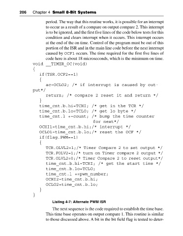
Listing 4-7: Alternate PWM ISR
The next sequence is the code required to establish the time base.
This time base operates on output compare 1. This routine is similar
to those discussed above. A bit in the bit field flag is tested to deter