
Page 282 - Programming Microcontrollers in C
P. 282
Timer Operations 267
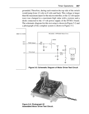
grounded. Therefore, during each rotation the top side of the switch
would jump from 12 volts to 0 volts and back. This voltage is larger
than the maximum input for the microcontroller, so the 12 volt square
wave was clamped to a maximum high value with a resistor and a
diode connected to the +5 volt power supply of the EVM11 board.
The schematic diagram for this test setup is shown in Figure 5-2 and
a photograph of the complete system is shown in Figure 5-3.
M6811C11EVM MC33033 - MPM3002 Motor Drive
33033
OC1 33k
PWM Output
OC3 Pin g
+5V 12V
1µƒ
33k
Time-Input
IC1
8.2k
.01
Magnet
Switch
Figure 5-2: Schematic Diagram of Motor Driver Test Circuit
Figure 5-3: Photograph Of
Assembled Motor Driver Test Circuit.