
Page 128 - Programming the Photon Getting Started With the Internet of Things
P. 128
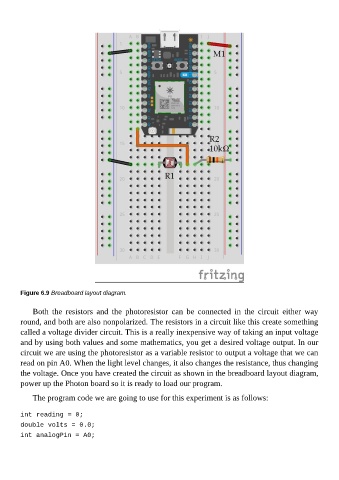
Figure 6.9 Breadboard layout diagram.


             Both  the  resistors  and  the  photoresistor  can  be  connected  in  the  circuit  either  way
        round, and both are also nonpolarized. The resistors in a circuit like this create something
        called a voltage divider circuit. This is a really inexpensive way of taking an input voltage
        and by using both values and some mathematics, you get a desired voltage output. In our

        circuit we are using the photoresistor as a variable resistor to output a voltage that we can
        read on pin A0. When the light level changes, it also changes the resistance, thus changing
        the voltage. Once you have created the circuit as shown in the breadboard layout diagram,
        power up the Photon board so it is ready to load our program.

             The program code we are going to use for this experiment is as follows:


        int reading = 0;

        double volts = 0.0;
        int analogPin = A0;