
Page 48 - Renewable Energy Devices and System with Simulations in MATLAB and ANSYS
P. 48
Solar Power Sources: PV, Concentrated PV, and Concentrated Solar Power 35
TABLE 2.2
Synchronous Machine Parameters for Dynamic Modeling
(Calculated Considering a Diesel Generator Set of 16 kVA)
Parameters Symbols Values
Resistances
Stator winding R a 0.0645 pu
Reactances
Stator leakage reactance X a 0.06 pu
Synchronous: direct axis X d 1.734 pu
Synchronous: quadrature axis X q 0.861 pu
Transient: direct axis X′ d 0.177 pu
Transient: quadrature axis X′ q 0.228 pu
Subtransient: direct axis X″ d 0.111 pu
Subtransient: quadrature axis X″ q 0.199 pu
Time constants
d: Transient T ′ d 0.018 s
d: Subtransient T ″ d 0.0045 s
q: Transient T ″ q 0.0045 s
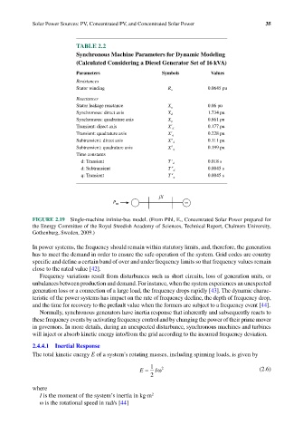
jX
P m ∞
FIGURE 2.19 Single-machine infinite-bus model. (From Pihl, E., Concentrated Solar Power prepared for
the Energy Committee of the Royal Swedish Academy of Sciences, Technical Report, Chalmers University,
Gothenburg, Sweden, 2009.)
In power systems, the frequency should remain within statutory limits, and, therefore, the generation
has to meet the demand in order to ensure the safe operation of the system. Grid codes are country
specific and define a certain band of over and under frequency limits so that frequency values remain
close to the rated value [42].
Frequency variations result from disturbances such as short circuits, loss of generation units, or
unbalances between production and demand. For instance, when the system experiences an unexpected
generation loss or a connection of a large load, the frequency drops rapidly [43]. The dynamic charac-
teristic of the power systems has impact on the rate of frequency decline, the depth of frequency drop,
and the time for recovery to the prefault value when the formers are subject to a frequency event [44].
Normally, synchronous generators have inertia response that inherently and subsequently reacts to
these frequency events by activating frequency control and by changing the power of their prime mover
in governors. In more details, during an unexpected disturbance, synchronous machines and turbines
will inject or absorb kinetic energy into/from the grid according to the incurred frequency deviation.
2.4.4.1 Inertial Response
The total kinetic energy E of a system’s rotating masses, including spinning loads, is given by
1
E = Iω 2 (2.6)
2
where
I is the moment of the system’s inertia in kg·m 2
ω is the rotational speed in rad/s [44]