
Page 215 - Reservoir Formation Damage
P. 215
196 Reservoir Formation Damage
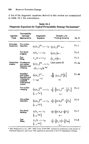
A list of the diagnostic equations derived in this section are summarized
in Table 10-1 for convenience.
Table 10-1
Diagnostic Equations for Typical Permeability Damage Mechanisms*
Permeability
Injection Damage Diagnostic Straight Line
Fluid Mechanisms Equation Plotting Scheme Eq. #
Particulate Pore surface
Suspension deposition (K!K \ - 1 - C t 2 T1 1
(K!K ^ vs t ~
Pore throat g i^ -\-C 6 t T1 2
plugging 1 ° (K/K )vs t ~
Pore / T1 3
filling ol 1 IK /K\vs.t ~
Particle-free Simultaneous / . 0/2 Least squares fit Tl-4a
solution pore surface \Kj K 0 ) = l + Cj
deposition and
sweeping _ fa + Cot)e e '
Simplified / , \i/2
/2
pore surface \K/K 0 ) = / (fi (K/K V l/fl T1 ~ 4b
deposition and ,
sweeping for 1 , r c ta te «
negligibfe " «
initial particle
content
Pore surface / >. \n /2 T1 5
sweeping \K/K 0) =1 + C 7 i f( V I/ \ ~
(l-,-V) vs. /
Pore surface / -^1/2 ( [x , v]/2 1 / ) Tl— 6
deposition \K/K 0) =1-09
(l-.-*^) vs. t
Pore throat ,,/., . n ( t/ , \ ~\ 1 ) T\ 1
K K =1 L
blocking I 0 - 1 ln\\ + \\K K. o\ — ll/C 7 > 11— /
ket
\l-e~ ) vs./
Pore K /K -I C f r/ , \ i / ) Tl-8
filling 01 10
(l-e et )
vs.t
* After Wojtanowicz et al., 1987, 1988; Civan, ©1992 SPE; reprinted by permission of the Society of
Petroleum Engineers, and Civan, 1994; reprinted by permission of the U.S. Department of Energy.