
Page 214 - Reservoir Geomechanics
P. 214
195 Compressive and tensile failures in vertical wells
comparison with Figure 6.13a, the result of moderate cooling makes it slightly easier
for drilling induced tensile fractures to be induced. That is, for a given value of S hmin ,
tensile fractures can occur at a slightly lower value of S Hmax .Of course, in geothermal
wells, where very significant cooling occurs, this effect can be much greater – so much,
in fact, that enlargements due to pervasive tensile failure have sometimes been mistaken
for breakouts in geothermal wells (D. Moos, personal communication). For the dril-
ling-induced tensile fractures in well D in the Visund field of the northern North Sea
◦
(Figure 6.7), wellbore cooling of ∼30 Cata depth of ∼2750 m resulted in σ
T = 1.7
θθ
MPa based on α = 2.4 × 10 −6 ◦ C −1 (corresponding to a rock composed of 30% quartz),
4
E = 1.9 × 10 MPa (from the measured P-wave velocity) and ν = 0.2 (based on the P-
to S-wave velocity ratio) (Wiprut, Zoback et al. 2000).
As noted above, mud weights above the pore pressure encourage the formation of
drilling induced tensile fractures. Figure 6.13c shows how 25 Cof wellbore cooling
◦
and 6 MPa of excess mud weight affect the formation of tensile fractures. Note that
modest increases in mud weight are much more influential on the formation of tensile
fractures than modest amounts of wellbore cooling. This will be important in Chapter 7
when we attempt to use observations of drilling-induced tensile fractures for estimating
the magnitude of S Hmax . Nonetheless, Pepin, Gonzalez et al.(2004) note that in a deep-
water Gulf of Mexico well, cooling seems to have decreased the frac gradient leading
to lost circulation.
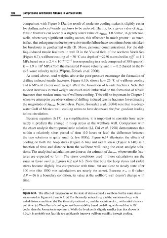
Because equation (6.17)isa simplification, it is important to consider how accu-
rately it predicts the change in hoop stress at the wellbore wall. Comparison with
the exact analytic thermoporoelastic solution (Li, Cui et al. 1998) demonstrates that
within a relatively short period of time (10 hours or less) the difference between
the two solutions is quite small (a few MPa). Figure 6.14 illustrates the effects of
cooling on both the hoop stress (Figure 6.14a) and radial stress (Figure 6.14b) as a
function of time and distance from the wellbore wall using the exact analytic solu-
tions. The analytical calculations are done at the azimuth of S Hmax , where tensile frac-
tures are expected to form. The stress conditions used in these calculations are the
same as those used in Figures 6.2 and 6.3. Note that both the hoop stress and radial
stress become slightly less compressive with time, but are close to steady state after
100 min (the 1000 min calculations are nearly the same). Because σ rr = 0 (when
P = 0) is a boundary condition, its value at the wellbore wall doesn’t change with
time.
←
Figure 6.14. The effect of temperature on the state of stress around a wellbore for the same stress
values used in Figures 6.2 and 6.3. (a) The thermally induced σ θθ and the variation of σ θθ with
radial distance and time. (b) The thermally induced σ rr and the variation of σ rr with radial distance
and time. (c) The effect of cooling on wellbore stability based on drilling with mud that is 10 ◦
cooler than the formation temperature. While the breakout is slightly smaller than that shown in
6.3c, it is probably not feasible to significantly improve wellbore stability through cooling.