
Page 23 - Reservoir Geomechanics
P. 23
8 Reservoir geomechanics
also generally true to the depth of the brittle–ductile transition in the upper crust at
about 15–20 km depth (Zoback and Zoback 1980, 1989; Zoback 1992). Assuming this
is the case, we must define only four parameters to fully describe the state of stress at
depth: three principal stress magnitudes, S v , the vertical stress, corresponding to the
weight of the overburden; S Hmax , the maximum principal horizontal stress; and S hmin ,
the minimum principal horizontal stress and one stress orientation, usually taken to
be the azimuth of the maximum horizontal compression, S Hmax . This obviously helps
make stress determination in the crust (as well as description of the in situ stress tensor)
a much more tractable problem than it might first appear.
Relative stress magnitudes and E. M. Anderson’s
classification scheme
In applying these concepts to the earth’s crust, it is helpful to consider the magnitudes of
the greatest, intermediate, and least principal stress at depth (S 1 , S 2 , and S 3 )in terms of
S v , S Hmax and S hmin in the manner originally proposed by E. M. Anderson and alluded to
above. As illustrated in Figure 1.2 and Table 1.1, the Anderson scheme classifies an area
as being characterized by normal, strike-slip or reverse faulting depending on whether
(i) the crust is extending and steeply dipping normal faults accommodate movement
of the hanging wall (the block of rock above the fault) downward with respect to the
footwall (the block below the fault), (ii) blocks of crust are sliding horizontally past
one another along nearly vertical strike-slip faults or (iii) the crust is in compression
and relatively shallow-dipping reverse faults are associated with the hanging wall block
moving upward with respect to the footwall block. The Anderson classification scheme
also defines the horizontal principal stress magnitudes with respect to the vertical stress.
The vertical stress, S v ,is the maximum principal stress (S 1 )in normal faulting regimes,
the intermediate principal stress (S 2 )in strike-slip regimes and the least principal stress
(S 3 )inreverse faulting regimes. The dip and strike of expected normal, strike-slip and
reverse faults with respect to the principal stress are discussed in Chapter 4.
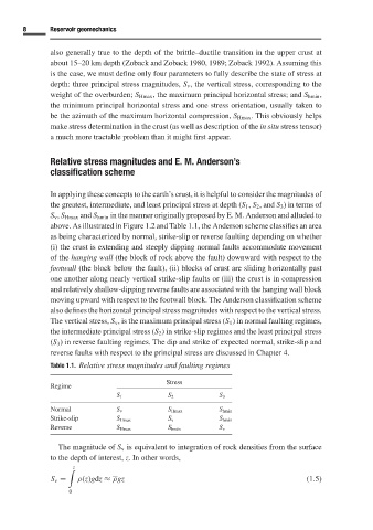
Table 1.1. Relative stress magnitudes and faulting regimes
Stress
Regime
S 1 S 2 S 3
Normal S v S Hmax S hmin
Strike-slip S Hmax S v S hmin
Reverse S Hmax S hmin S v
The magnitude of S v is equivalent to integration of rock densities from the surface
to the depth of interest, z.In other words,
z
S v = ρ(z)gdz ≈ ρgz (1.5)
0