
Page 111 - Robotics Designing the Mechanisms for Automated Machinery
P. 111
100 Dynamic Analysis of Drives
the shortest possible time followed by locking of the drive as soon as the moving
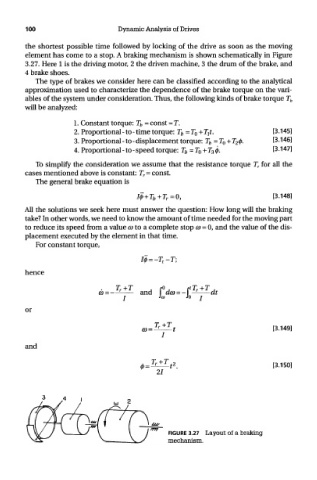
element has come to a stop. A braking mechanism is shown schematically in Figure
3.27. Here 1 is the driving motor, 2 the driven machine, 3 the drum of the brake, and
4 brake shoes.
The type of brakes we consider here can be classified according to the analytical
approximation used to characterize the dependence of the brake torque on the vari-
ables of the system under consideration. Thus, the following kinds of brake torque T b
will be analyzed:
To simplify the consideration we assume that the resistance torque T T for all the
cases mentioned above is constant: T r = const.
The general brake equation is
All the solutions we seek here must answer the question: How long will the braking
take? In other words, we need to know the amount of time needed for the moving part
to reduce its speed from a value CD to a complete stop CD = 0, and the value of the dis-
placement executed by the element in that time.
For constant torque,
hence
or
and
FIGURE 3.27 Layout of a braking
mechanism.