Page 508 - Rock Mechanics For Underground Mining
        P. 508
     MINING-INDUCED SURFACE SUBSIDENCE
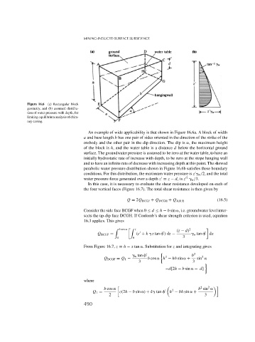
              Figure 16.6 (a) Rectangular block
              geometry, and (b) assumed distribu-
              tion of water pressure with depth, for
              limiting equilibrium analysis of chim-
              ney caving.
                                          An example of wide applicability is that shown in Figure 16.6a. A block of width
                                        a and base length b has one pair of sides oriented in the direction of the strike of the
                                        orebody and the other pair in the dip direction. The dip is  , the maximum height
                                        of the block is h, and the water table is a distance d below the horizontal ground
                                        surface. The groundwater pressure is assumed to be zero at the water table, to have an
                                        initially hydrostatic rate of increase with depth, to be zero at the stope hanging wall
                                        and to have an infinite rate of decrease with increasing depth at this point. The skewed
                                        parabolic water pressure distribution shown in Figure 16.6b satisfies these boundary
                                        conditions. For this distribution, the maximum water pressure is z   w /2, and the total
                                                                                        2
                                        water pressure force generated over a depth z = z − d,is z   w /3.
                                          In this case, it is necessary to evaluate the shear resistance developed on each of
                                        the four vertical faces (Figure 16.7). The total shear resistance is then given by
                                                            Q = 2Q BCGF + Q DCGH + Q ABFE             (16.5)
                                        Consider the side face BCGF when 0 ≤ d ≤ h − b sin  , i.e. groundwater level inter-
                                        sects the up-dip face DCGH. If Coulomb’s shear strength criterion is used, equation
                                        16.3 applies. This gives
                                                      %  b cos     %  z            (z − d) 2
                                              Q BCGF =           (c + k  z tan   )dz −      w tan   dx
                                                       0       0                      3
                                        From Figure 16.7, z = h − x tan  . Substitution for z and integrating gives
                                                                 w tan         2          b 2  2
                                                  Q BCGF = Q 1 −      b cos   h − hb sin   +  sin
                                                                  3                        3
                                                                              −d[2h − b sin   − d]
                                        where
                                                                                                  2
                                                                                              2
                                                 b cos                            2          b sin
                                            Q 1 =        c(2h − b sin  ) + k  tan      h − bh sin   +
                                                    2                                           3
                                        490
     	
