Page 564 - Rock Mechanics For Underground Mining
P. 564
MONITORING ROCK MASS PERFORMANCE

                                        surfacesubsidenceassociatedwithundergroundextraction.Satellite-basedGlobalPo-
                                        sitioning Systems (GPS) may also be used for the latter purpose (e.g. Collier, 1993,
                                        Windsor, 1993). In the past, considerable use was made of photoelastic plugs and discs
                                        to monitor stress changes in the rock surrounding excavations and in support elements.
                                        Details of several of these photoelastic instruments are given by Roberts (1977).
                                          Hydraulic and pneumatic diaphragm transducers are used for measuring water
                                        pressures, support loads, cable anchor loads, normal components of stress and set-
                                        tlements. In all cases the method of operation is the same. The quantity measured
                                        is a fluid pressure which acts on one side of a flexible diaphragm made of a metal,
                                        rubber or plastic. Twin tubes connect the read-out instrument to the other side of the
                                        diaphragm. To take readings, air, nitrogen or hydraulic oil pressure is supplied from
                                        the read-out unit through one of the tubes to the diaphragm. When the supply pressure
                                        is sufficient to balance the pressure to be measured, the diaphragm acts as a valve and
                                        allows flow along the return line to a detector in the read-out unit. The balance pressure
                                        is recorded, usually on a standard Bourdon pressure gauge or a digital display.
                                          Electrical devices probably provide the most common basis of the instruments
                                        presently used to monitor the performance of rock masses surrounding mining struc-
                                        tures, although mechanical systems still find widespread use in displacement moni-
                                        toring. Electrical systems generally operate on one of three basic principles.
                                          ElectricresistancestraingaugesoperateonaprinciplediscoveredbyLordKelvin,
                                        namelythattheresistanceofawirechangesproportionatelywithstrain.Instraingauge
                                        systems, strain gauges made from thin wire or foil, are bonded to a rock, concrete or
                                        steel surface. Changes in the strains in the host material are accompanied by changes
                                        in the strains, and resistances, of the strain gauges which are read using a Wheatstone
                                        bridge circuit.
                                          The use of electrical resistance strain gauges in the measurement of in situ stresses
                                        was discussed in section 5.3. Most load cells, many pressure transducers and some
                                        types of inclinometer also use electrical resistance strain gauges. The major disadvan-
                                        tages associated with the use of electrical resistance strain gauges for rock mechanics
                                        applications are
                                        (a) it is difficult to obtain and maintain a good bond between the strain gauge and
                                            the rock,
                                        (b) the strains are measured over relatively short gauge lengths, and
                                        (c) temperature effects cannot always be eliminated.
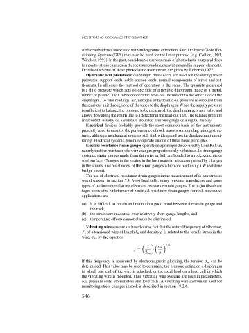
                                          Vibrating wire sensors are based on the fact that the natural frequency of vibration,
                                        f , of a tensioned wire of length l w and density   is related to the tensile stress in the
                                        wire,   w , by the equation
                                                                                1/2

                                                                       1      w
                                                                 f =
                                                                      2l w
                                        If this frequency is measured by electromagnetic plucking, the tension   w can be
                                        determined. This value may be used to determine the pressure acting on a diaphragm
                                        to which one end of the wire is attached, or the axial load on a load cell in which
                                        the vibrating wire is mounted. Thus vibrating wire systems are used in piezometers,
                                        soil pressure cells, stressmeters and load cells. A vibrating wire instrument used for
                                        monitoring stress changes in rock is described in section 18.2.6.
                                        546

