
Page 192 - Root Cause Failure Analysis
P. 192
180 Root Cause Failure Analysis
Figure 14-12 Straight or plain bevel gear (Neale 1993).
direction as straight-bevel gears. This type of gear permits slight errors in assembly
and some displacement due to deflection under load. Zero1 gears should he used at
speeds less than 1,000 ft per minute because of excessive noise at higher speeds.
Spiral
Spiral-bevel gears (Figure 14-1 3) have curved oblique teeth that contact each other
gradually and smoothly from one end of the tooth to the other, meshing with a rolling
contact similar to helical gears. Spiral-bevel gears are smoother and quieter in opera-
tion than straight-bevel gears, primarily due to a design that incorporates two or more
contacting teeth. Their design, however, results in high tooth pressure.
This type of gear is beginning to supersede straight-bevel gears in many applications.
They have the advantage of ensuring evenly distributed tooth loads and carry more
load without surface fatigue. Thrust loading depends on the direction of rotation and
whether the spiral angle of the teeth is positive or negative.
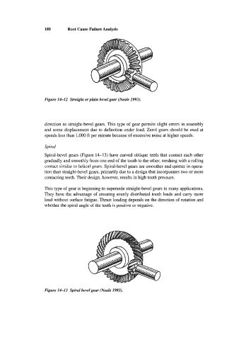
Figure 14-13 Spiral bevel gear (Neale 1993).