
Page 115 - Safety Risk Management for Medical Devices
P. 115
94 Safety Risk Management for Medical Devices
12.6.1.1 Set scope
The scope defines the boundary of the analysis, for the subject of analysis. For exam-
ple, if you intend to analyze a defibrillator, include all parts of the product including
packaging, in the scope of analysis. Then decompose the scope into its constituent
elements. The granularity of this decomposition is your choice. You could choose to
analyze at the detailed components level (e.g., a capacitor), or at an intermediate
architectural level (e.g., power supply). Each element within the scope of analysis
should be cited in the DFMEA template as an item, and analyzed for its Failure
Modes and effects. It is permissible to have different depths of decomposition among
the elements in the scope of analysis.
The scope of analysis should include the Failure Modes of each item, as well as
Failure Modes of the interfaces among the items.
There are four types of interfaces between elements:
1. Physical interface—e.g., mechanical connections
2. Energy interface—e.g., electrical; thermal
3. Data interface—e.g., alerts; information; bit stream
4. Mass interface—e.g., fluids; gases
Energy, data, and mass are typically transmitted via physical interfaces among the
elements, e.g., via wires, or tubes. Let’s call the thing that is transmitted, “payload.”
For instance, the payload for a wire could be electrical energy, or data; and the pay-
load for a tube could be a fluid or a gas. The physical interface should be considered
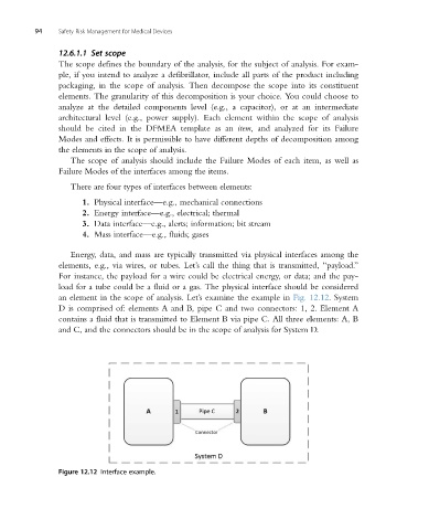
an element in the scope of analysis. Let’s examine the example in Fig. 12.12. System
D is comprised of: elements A and B, pipe C and two connectors: 1, 2. Element A
contains a fluid that is transmitted to Element B via pipe C. All three elements: A, B
and C, and the connectors should be in the scope of analysis for System D.
Figure 12.12 Interface example.